Meta Description: This article will describe the 12 commonest types of holes used in engineering, including their hole diameter, like blind holes, through holes, counterbore, countersink and tapped holes among others. Find out how to use them, their symbols, and machining processes to have the best production outcomes.
Introduction to Engineering Holes
Hole engineering could be one of the most basic characteristics of manufacturing and machining processes. These are specifically machined openings which find an infinite number of uses in all types of industries such as in the aerospace and automobile manufacturing industries. Their proper knowledge of the different types of holes, their particular applications is imperative to the engineers, machinists, and designers of mechanical components.
Holes Machining A hole in engineering is an opening in the form of a circle formed by a rotating cutting tool, and its hole depth is crucia but other shapes are possible in modern manufacturing processes. More holes imply the functionality, safety and performance of manufactured parts thus affecting the precision and accuracy of these holes.
Understanding Hole Classifications in Manufacturing
In engineering holes are termed using various important characteristics such as depth, shape, surface finish and that which they are supposed to perform. The characteristics of any type of hole are location, diameter, depth, and tolerances. These categories assist engineers to make good judgments in choosing proper machining procedures and to perform best in their end applications.
The technology used in creating holes such as CNC technology, precision tooling and computer-aided design have been improved and a significant change in manufacturing processes has occurred. Both types of holes have various matters of consideration regarding tool selection, cutting parameters and quality checks.
Basic Hole Geometry and Terminology
In order to discuss the particular types of holes, one has to be familiar with the basic geometry and engineering drawings and specification terms. Parameters that make up hole geometry are diameter, depth, chamfer angle, surface roughness and position tolerances.
Terminologies applicable in hole specifications are internationally established so that information among the designers, manufacturers, and quality control people are always in consistency. It is important to know the terms in order to understand engineering drawing and be able to interpret it well with satisfactory results on manufacturing.
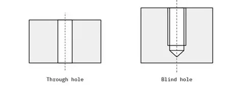
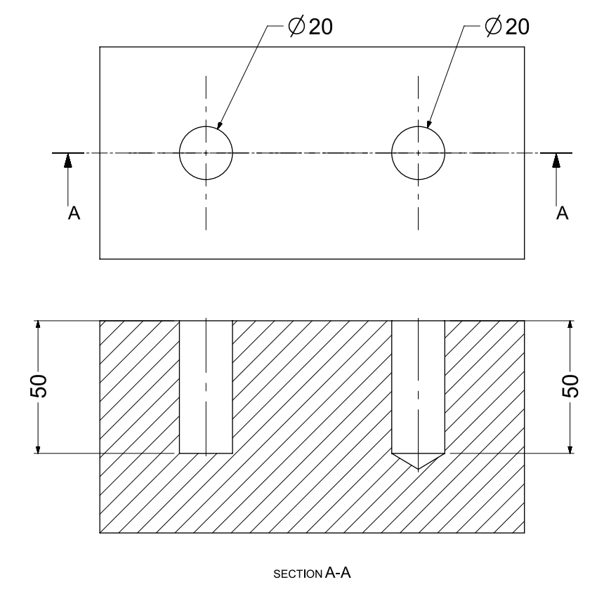
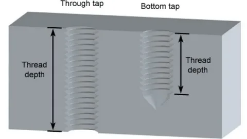
1. Blind Holes: Partial Penetration Features
Blind hole is a hole, which does not pass fully through the material. This shape has been reamed, drilled, or milled to a certain depth and not through the other-side of the workpiece. One of the most common features in mechanical engineering work is the blind holes.
The depth of blind holes can be provide as total depth measured against surface or the thickness of material left in bottom of hole. This specification freedom gives the designer freedom to optimise material use and structural strength.
Blind Hole Manufacturing Processes
Blind holes can be machined in CNC milling machines by a thread milling cycle. The threading of blind holes is done in three ways and they include conventional tapping, single-point threading and helical interpolation. All the methods have their particular benefits, based on the material, hole bandwidth, precision needed.
The most popular procedure of making threaded blind holes is conventional tapping, especially in manufacturing facilities. Single-point threading such as, helical interpolation, however, is less sensitive to control, and may work with more recalcitrant material or more stringent tolerances.
Applications of Blind Holes in Engineering
Blind holes perform many vital roles in an engineering context, particularly in the use of threaded fasteners . They are more frequently applied to hold components in a location where through-holes would interfere with structural and/or cosmetic integrity, or where the screw head would be concerned . Blind holes are a common fastening technique used in electronic housings, automotive parts and aerospace construction because no total penetration is required.
Blind holes play an important role in engineering since they can be utilized to measure residual stresses; hence they find usefulness in stress analysis and materials testing. The ability to measure this is vital especially in high stress applications where the performance of the material used should be monitored thoroughly.
2. Through Holes: Complete Penetration Features
A through hole A drilled hole is a hole drilled to pass entirely through the material. The through hole passes entirely through the work piece. It can be referred to as thru-hole. They give total access to both sides of the material and is necessary in most mechanical assemblies.
Through holes are generally simpler to make than blind holes, because one does not normally need to worry about tool depth control, and chip clearing is more effective. The whole penetration is also facilitated with ease of inspection and quality supervision.
Through Hole Specifications and Symbols
The symbol used to specify a through hole is the diameter symbol (2) symbol. Engineering drawings display through holes through providing the diameter of the hole and its depth. To take an instance, an opening 10 diameters continued through the component would be indicated as: 10 diameter through hole.
This universally applicable notation would enable unrestricted communication between the design and manufacturing units and minimise the chances of misinterpretation and manufacturing error. The word Through is used to clearly state that total penetration has been specified, whereas in blind hole specifications no penetration is required.
Electronic Applications of Through Holes
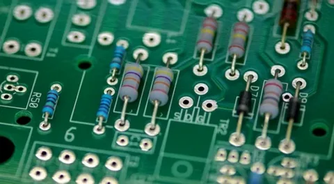
Engineers use through holes in many ways. As an example, holes are commonly used to accommodate electronic components (e.g. holes drilled in printed circuit boards (PCBs)). Through holes are used in electronics industry to mount components and connect layers of the circuit using electricity.
Electronic through holes often also demand high precision, frequently to the micrometer. High-performance level drilling methods and tooling are used to attain these challenging requirements and assure production efficiency.
3. Interrupted Holes: Complex Machining Challenges
An interrupted hole An interrupted hole is a hole in which another feature crosses the hole. A fresh hole-making process drills in a series of coaxial holes in the workpiece (gaps in the material are replaced by the sheer Nothingness). Intermittent nature of cutting action during the manufacture of these holes poses special difficulty.
The best strategy in dealing with interrupted holes is to ensure that cutting tool selection, cutting tools, speeds, and feeds are properly considered so that they do not cause problems to the tool damage. In case of the intermittent cutting action it is a factor that may result in vibration of the tool, and premature wear of the tool unless it is controlled properly.
Manufacturing Considerations for Interrupted Holes
Drilling cycles consist of non- and cutting moves which have to be designed with advanced programming and machine control. CNC programs need to be prepared to execute the non-cutting and cutting stages with an equilibrium so that the holes quality and the tool life are retained.
During the interruption of hole machining, particular emphasis has to be placed on the evacuation of chips and coolant delivery. These material gaps may lead to interrupted coolant flow and chips may build up which may damage the tool or leave a bad finish on the surface.
4. Simple Holes: Fundamental Circular Features
Simple hole in engineering is a circle whose hole has been taken out of an object. There exist various types. The symbol that represents a simple hole is the one that is in the form of 0. In engineering drawings simple holes are expressed by providing the diameter of the hole and the particular depth of the hole.
The basic hole shapes serve as a base of the complicated geometry of holes and in most hole-making production processes these mass-basic holes are used as the initiation hole of the entire process. They can be easily and readily produced in large quantities and volume manufacturing systems because of their simple geometry.
Versatility of Simple Holes in Design
Depending on how they are utilized, simple holes have numerous different uses in the world of engineering such as making holes where fasteners can be put. The other use is as parts. The flexibility of the simple holes has helped to make them one of the most common features to be specified in engineering drawings in any industry.
Cutting simple holes is an activity that has been perfected over the last 100 years with the advancement of cutting tool technology, machine tool design and process development. Simple holes made with modern CNC based systems have the highest level of accuracy and repeatability in production.
5. Counterbore Holes: Recessed Fastener Solutions
The counter bore hole is a simple hole, with a wider hole which is linked to it above, and it serves as a standard screw hole . It is a routine screw hole. The callout designator of the counterbored holes sign is ‘ 0 1 4 . Symbol and number of depth are also added. Counterbore holes facilitate fasteners to be placed below the surface or in line with it.
Counterbore holes have a geometry of two-steps and this means that alignment has to be made between the counterbored recess and the pilot hole. The correct position of fasteners through their seating and distributed loads depend on such alignment.
Applications and Manufacturing of Counterbore Holes
PCBs can be counterbored. This kind of hole is applied in this case in the machining process of socket-head screws. The counterbore holes are applied in the case in which the bolt or screw has to lie below the surface.
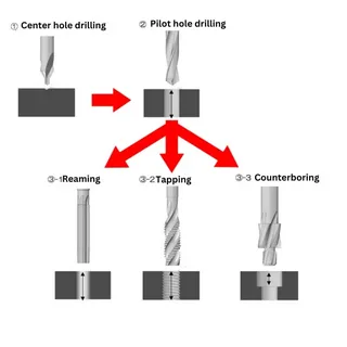
The practice is to manufacture counterbore holes by making a first hole (pilot hole) after which one uses a counterbore tool to cut a bigger recess. There are specialised tools that may allow both operations to be found at the same time enhancing efficiency and accuracy.
6. Spotface Holes: Surface Preparation Features
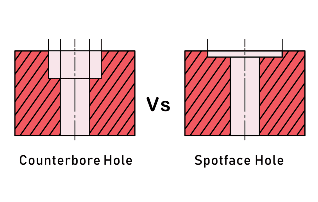
Spotface hole: This hole resembles counterbole hole war it is shallow. It permits fastener to rest flat. Spotface holeThe spotface hole callout symbol consists of the counterbore symbol of the number sign, 1816; with the letters SF inside. Spotface holes are more used to prepare the surface than to hide the fasteners.
The flatness of spotface holes can be used where a large flat bearing surface is required without necessarily compromising the thickness of a material. This is of interest especially in thin walled cross sections or structures where there should be minimum removal of materials.
Spotface Applications in Rough Surfaces
Spotfaces Come in hand in the field of engineering in order to generate a smooth planar surface on a machined piece. A casting part can not be as smooth and flat as a machined component. What this implies is that a spotface hole is drilled, which ensures that the work which must be bonded with another component with a rough surface is accurately placed.
There are usually irregularities on the surface of cast components that do not allow the proper seating of fasteners. Spotface cutting operations make local-flat surfaces that provide good contact of the fasteners and the distribution of the loads without the cost of machining the entire surfaces.
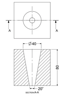
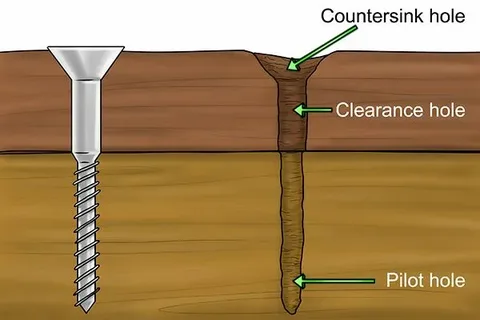
7. Countersink Holes: Conical Fastener Accommodation
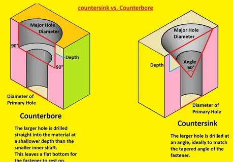
Instead of counterbore hole, a countersink hole has a more conical shape. A countersunk hole is an easy hole having a cone hole above it. This cone-shaped hole needs slightly more machinery and attention to calculate as compared to drilling a counterbore hole.
The countersink holes are angular in geometry to the angle of the heads of the countersunk fasteners which are usually 82, 90, or 100. Such exact angle locks are critical in the correct seating of fasteners and the best transfer of loads.
Countersink Hole Specifications and Applications
Countersink hole A countersink hole is indicated by a callout symbol of 106. In engineering these are Countersunk types where a countersunk bolt or screw is needed. Countersink holes are holes such as counterbore holes that enable a screw or a bolt to be below the surface.
Countersink holes are common in aerospace where external smooth surfaces are very important in aerodynamics. The design of the conical shape gives the best stress dispersion and preserves the structural strength of a thin-walled dimension.
8. Counterdrill Holes: Combined Recess Features
A counterdrilled hole is similar in that it has a recess above it but is in contrast to a countersink hole. The callout symbol of a counterdrill hole is identical to that of a countersink: ‘a h depth is listed, thus. The design is a variation of both countersink and counterbore geometries to have their advantages.
Counterdrill hole is specifically beneficial where the common countersink angles would not equitably open the clearance beams to installer the fasteners heads or when extra or additional distances into the recesses would be demanded in a set application.
Manufacturing and Application Benefits
Computer-1 When one needs to have a counter sunk bolt or screw, countersunk holes with a circular cross section , similar to counterdrill holes, are used in engineering. Moreover, they are widely applied to PCBs. The extra recess is a provision of space to accommodate the fastener heads without compromising the angular geometrical form to seat accordingly smooth and flat surface.
Counterdrill hole can be used in electrical connections to accept component leads or give clearance of solder connections as well as retain the mechanical advantages of the countersunk mounting fasteners hole features.
9. Tapered Holes: Variable Diameter Features
Tapered hole-here the start diameter of a hole is not as wide as the end diameter of the hole. It is broad at one side as compared to the other. A tapered hole has a triangle with a line marking it as the call out symbol. The end ratio and diameter are also mentioned.
The tapered holes need special tooling and machining skills to make the taper angle and finish in a specific way. The tapering operation requires the manufacturing process to very well control their feeding rate and cutting parameters during manufacturing.
Applications of Tapered Holes in Tooling
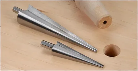
Engineering application of tapered holes is employed in numerous applications. The most common example is to fasten the cutting tools or other tool holders. Tapered connections are self locking giving good repeatability and rigidity within tool holding applications.
The value is the taper ratio of the typical holes used to mount cutting tools on machine tool spindles, though there are standard ratios which imply interchangeability of the cutting tools made by different manufacturers as well as in the producer of said holders. Such standardisation is important regarding the flexibility of manufacturing and management of tool inventories.
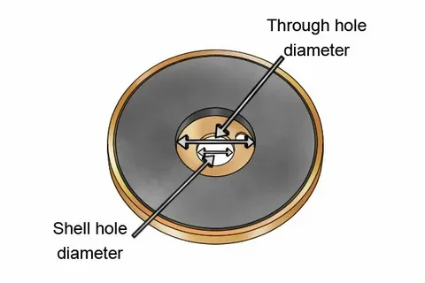
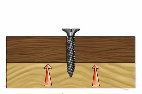
10. Screw Clearance Holes: Fastener Passage Features
A screw clearance hole is simply a hole with a little large diameter than that of a screw thread in such a way that it allows the screw to get through. It is a hole large enough to permit passage of threads of a screw or bolt but not the head of the screw or bolt being used.
Essentials in assembly and functionality of clearance holes include sizing. If it is too small, then the fastener won t find its way through and if it is too big then the connection might not be as precise or strong.
Clearance Hole Sizing Calculations
It computes the size of a screw clearance hole, by summing the diameter of the screw and the diameter of the screw head, and dividing the sum by two. The application of this procedure of choosing the size will provide the greatest hole which will go beneath the head of fastener.
This formula gives a best guarantee method of sizing clearance holes so as to offer sufficient clearance and also have proper engagement of the fasteners. But certain applications might need modifications according to tolerances requirements and conditions of assembly.
Manufacturing and Applications of Clearance Holes
Most CNC milling machine can make a clearance hole on a screw. In engineering, screw clearance holes accommodate the parts where the screw or the bolt must pass through. Clearance holes are also easy to produce in large volumes at standard drilling processes.
The assemblies used in mechanical constructions everywhere involve the use of clearance holes, which are used to connect various elements using threaded screws. One of the most prevalent types of holes is applied across all manufacturing industries due to its prevalence.
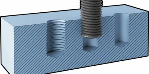
11. Tapped Holes: Internal Threading Solutions
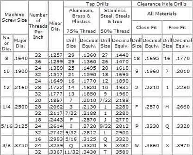
Tapped hole is a hole that is drilled then a machine screw fits through it. It is made by creating threads by cutting on the inside of the hole by tapping. They are applied in engineering on metals where a nut and bolt cannot be applicable.
Material, cutting fluid and tool wear should be carefully considered during the tapping so that the quality of threads can be replicated regularly. It is necessary that the poor design and cutting parameters must be avoided to prevent thread damage and excellent connections.
Tapped Hole Specifications and Symbols
The callout symbol of a tapped hole, metric holes, discusses that the diameter symbol is replaced with an M. In other types of thread e.g. a Unified National Fine (UNF) thread, the number dimension is denoted first followed after by a list that states the type of thread e.g. UNF.
Thread characteristics should be given such as pitch, fit class and the engagement length, to allow proper identification of the fasteners and assembly practices. These requirements pose important specifications to deliver the demanded mechanical properties of threaded connection.
Tapping vs. Threading Process Differences
Tapped and threaded holes are almost similar but using two forms of machining processes. The distinction between the threading and tapping is in the instrument and in surface where the operations occur. Threading involves the production of threads on a die tool that occurs on a hole. Threads are created through a tapping tool in a drilled hole in the tapping process.
This distinction is significant to process planning and the process of tooling choice. There are various considerations on chip evacuation, the delivery of the cutting fluids, as well as tool wear during the tapping operations as opposed to external threading operations.
12. Threaded Holes: Advanced Internal Threading
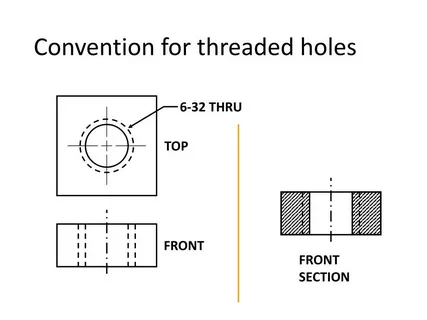
Threaded holes are holes that are threaded. They are like the tapped holes but differ in the manner of manufacture. Threaded holes In mechanics Threaded holes are standard elements in parts that are fastened mechanically. CNC machines are easy to add.
Contemporary CNC devices provide several options of creating threaded hole creation, and the conventional techniques are combining a tap with tapping, thread milling, and thread forming operations. Any of the methods has its advantage with reference to the material, size of holes, and production needs.
Manufacturing Sequence for Threaded Holes
Addition of threads will be the final stage when most other constituents of the part are already machined. This ordering avoids damage to the threads by additional machining processes and guarantees best quality of thread on the final part.
Thread operations in the manufacturing cycle should be timed to accommodate requirements of work holding element of manufacturing, availability of tools and quality control process to bring them to a point of adequacy accomplished in all part features.
Threaded Hole Specifications and Standards
Threaded holes may be called out using the diameter symbol: ’01. The diameter symbol is replaced by an M, when they are metic. The written depth is threaded. Such specifications should meet applicable norms so that they can be compatible with standard fasteners.
International threaded hole standards specify dimensional needs, tolerance grades and inspection procedures. They are necessary to ensure interchangeability and mechanical connection reliability worldwide manufacturing.
Advanced Hole Machining Techniques
In modern manufacture hole making methods have been advanced with electrical discharge machining (EDM), laser drilling and using waterjet cutting. Depending on the needs in precision and properties of materials, one will apply CNC drilling, punching, tapping, broaching, and EDM drilling.
The holes made using such advanced methods can be made on materials that are hard to produce holes on using more traditional methods, these materials include hardened steels, ceramics or composite materials. All the techniques present different strengths to the different applications and material combinations.
Quality Control and Inspection Methods
Engineered holes quality control Quality control of engineered holes is performed by dimensional checking, examination of surface finish, and running functional tests. Modern CMMs (coordinate measuring machines) and optical measurement systems offer precise data measuring and the most challenging tasks.
The statistical process control techniques allow producers to keep holes of similar quality in massively produced runs. Such approaches give an indication of trends and variations that may cause quality problems; they do it even before the finished products are affected by these problems.
Material Considerations for Hole Machining
Various materials adopt varied hole machining with reference to aspects on their hardness, thermal conductivity and chip forming attributes. Aluminium alloy, stainless steels, titanium and composite materials all have their problems and possibilities during the process of hole machining.
Tool selection, cutting conditions and coolant strategies have to be specifically optimized on any material to meet the desired types of holes quality at reasonable production rates and tool life.
Tooling Technology for Hole Making
The field of cutting tool technology is ever advancing and new coating, geometries and materials are being developed which are making advancements towards higher performance of hole-making operations. The tool types such as carbide, ceramic and polycrystalline diamond have their benefits based on the application consumed.
Tool life optimization is a process of balancing between the cutting speed, feed rate and the tool geometry in order to attain maximum productivity and at the same time maintaining the quality of the hole. Advanced monitoring technologies of tools aid in determination of the best cutting conditions as well as forecast of the wear condition of the tools.
Automation in Hole Manufacturing
Automated hole making systems combine robot loading, CNC machining and quality control to produce very efficient production cells. Mixed and complicated parts and geometries can be produced and also kept at the same quality using these systems.
Artificial intelligence / machine learning, when applied in hole manufacturing, allows predictive maintenance, optimization of processes and prediction of quality with the help of real time analysis of data.
Design Guidelines for Engineered Holes
The good hole design involves right treatment of stress-concentration, removal of material, and manufacturing capability. The design constraints will assist the engineers to optimize where to place holes, their size, and geometry in terms of functional requirements, as well as production requirements.
The finite element analytical tools provide the advantages of designers being able to calculate stress concentration around holes and provide designs which are ideal strengths but weigh minimum. The tools are also useful in aerospace and automotive industry where weight reduction is essential.
Cost Optimization in Hole Manufacturing
Cost optimization implies a trade-off between hole requirements and producibility to meet the desired performance at the low cost. These involve the tolerance requirements, surface finish requirement and volume counting at the design stage.
Value engineering methods aids in the opportunity to simplify the hole specifications without affecting functionality. To some degree, standard hole sizes, common tooling, and standard processes yield major cost benefits compared to customized solutions.
Future Trends in Hole Technology
Recent innovations in the world of additive manufacturing, hybrid machining, and the development of advanced materials are formulating new opportunities to make counter drill holes and design them. Such technologies might realize geometries impossible before, or obviate the conventional hole-making process in others.
Polymorphous holes In research on smart materials and adaptive structures, there is a possibility to create holes which may be bigger or alter their shape with the operation circumstances. The applications in the spheres of aerospace, automotive, and biomedical engineering could become revolutionized by these developments.
Environmental Considerations
Energy and coolant application should also be minimized in hole making hence sustainable manufacturing plays a role in ensuring proper tool life optimization as well as an energy reduction. Environmental regulation is increasing the usage of dry machining and minimum quantity lubrication (MQL) methods.
Re-use and recycling of the cutting tools and cutting fluids helps to lower the environmental usage as is also likely to minimize the cost of cutting. The use of life cycle assessment tools enables manufacturers to analyze the overall environmental effect of hole-making process at a manufacturer.
Training and Skill Development
The machining of holes in this day and age is a sophisticated process that needs trained operators and programmers who have knowledge when it comes to the old machining principles and advanced CNC machine process. The training should not only focus on the theoretical information or expertise but also practical abilities.
Training on costly tall equipment and material is done safely on the simulation soft wares. The technologies of virtual reality and augmented reality are already entering the advanced manufacturing training programs.
Industry-Specific Applications
Each industry has its own holes specifications and manufacturing requirements. Aerospace applications require high precision and product traceability whereas the automotive industry needs to produce products in large volumes with the highest efficiency.
The production of medical devices calls upon using biocompatibility materials and surfaces and usually involves specially designed hole manufacture procedures. The electronics industries require small scale holes with good quality surface finish and accuracy of dimensions.
Conclusion
Various holes types in engineering are basic bricks in the modern manufacture and mechanical design. They range in simplicity with through holes to more complex tapered holes or threaded holes and all holes have their functional purpose and result on unique manufacturing challenges and opportunities.
Knowledge of how each type of hole can behave, what it can be used in, and what has to be taken into consideration during manufacturing a hole, can help the engineers and manufacturers base their decision with the aim of supporting the maximum performance of the product, as well as the process of its manufacturing. With the ongoing development of the conditions of manufacture, it is obvious that the accuracy, complexity, and variety of designed holes will only grow, bringing new horizons of the innovative solution of design requirements.