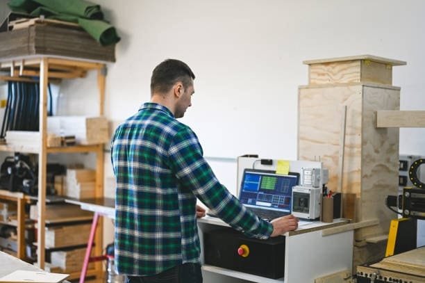
Modern manufacturing depends critically on machining design, which forms the basis for manufacturing exact, robust, and high-performance parts. Machining design has changed to satisfy needs in sectors including aerospace, automotive, healthcare, and consumer electronics as technology developed. To enable engineers and manufacturers increase efficiency and product quality, this blog will investigate the fundamental ideas, key components, best practices, common challenges, and future trends in machining design.
Understanding Machining Design
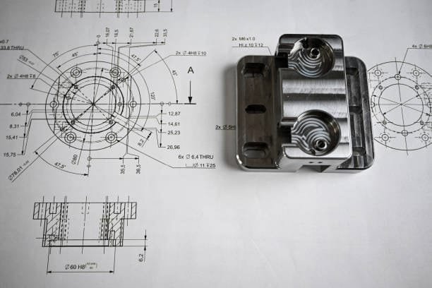
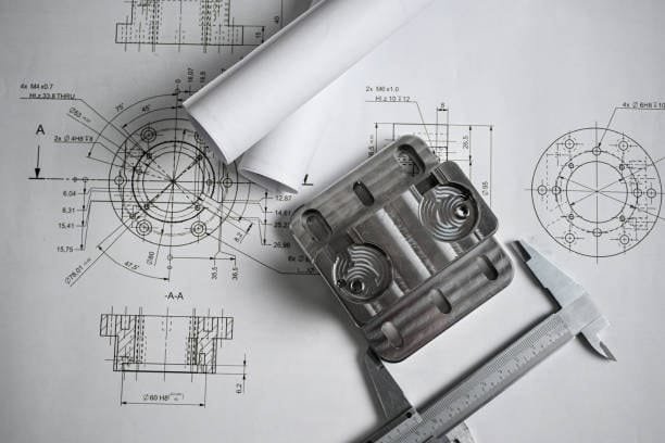
Machining design is the process of producing precise plans technical drawings and specifications for manufacturing parts by several machining techniques. Designing elements that can be precisely manufactured with few mistakes while yet guaranteeing best performance is the aim.
Important machining design factors include:
- Material Selection: Selecting the correct material to fit the intended use of the part requires thought.
- Tolerances and Surface Finish: Guaranturing exact measurements and flawless finishes.
- Tooling and Fixturing: Designing efficient tools and fixtures for stability during machining requires consideration of tooling and fixtering.
- Machine Capabilities: Maximizing accuracy and efficiency requires matching the design with machine tool capabilities.
Essential Elements of Machining Design
1. Material Selection
In machining design, selecting the suitable material is absolutely important. Various materials provide different difficulties:
- Metals: Commonly used for their strength and durability are metals including copper, titanium, aluminum, and steel. To prevent tool wear and guarantee smooth finishes, metals call for exact cutting speeds and tool selection.
- Plastics: Though they are lightweight and flexible, plastics call for specific machining techniques. Under great heat, plastics are prone to melting or deforming; hence, careful tool speed control and cooling techniques are needed.
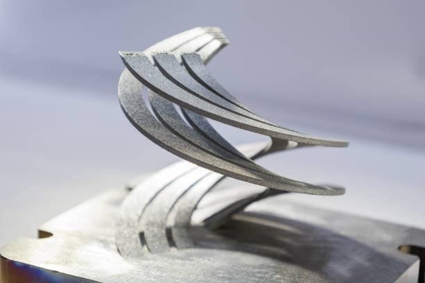
- Composites: Used in aerospace and automotive sectors increasingly for their strength-to—-weight ratio, composites Because of their abrasive character, composites can be difficult to machine and call for specific tools with diamond-coated tips or carbide inserts.
Tip: Knowing the machinability, thermal qualities, and structural integrity of the material guarantees the best possible design choices.
2. Dimensional Tolerances
Tolerances specify reasonable ranges for part dimensions. While great accuracy is guaranteed by tight tolerances, too high precision can raise manufacturing costs. By selecting reasonable tolerances for every feature, designers can strike a mix between cost economy and accuracy.
- Commonly used for non-critical features where accuracy is not absolutely required are standard tolerances.
- Applied in aerospace, medical, and precision instruments where accuracy is vital, tight tolerances define these devices.
3. Surface Finish
Parts needing low friction, better appearance, or increased performance must have a smooth surface finish. The kind of machining operation—milling, turning, grinding—will affect the surface finish that can be obtained.
- Usually producing a coarse finish, roughing operations are perfect for stages of material removal.
- Focused on obtaining smooth surfaces with minimum defects, finishing operations

4. Tool Path Optimization
To reduce machining time and maximize accuracy, designers should map effective tool paths. Well-optimized tool paths lower tool wear, raise accuracy, and increase output.
- Effective on flat surfaces but may leave tool marks from zigzag tool paths.
- Perfect for circular or curved parts, spiral tool paths give even finishes.
- Advanced tool path methods known as adaptive clearing strategies maximize cutting speed and reduce vibration.
5. Fixture Design
Keeping parts firmly during machining depends on fixtures. Good design of a fixture reduces vibration and improves stability, so improving accuracy.
- Modular Fixtures: Flexible configurations meant to allow several part configurations define modular fixtures.
- Dedicated Fixtures: Custom fixtures specifically for high volume manufacturing help to guarantee repeatability.
Best Practices When Designing Parts With CNC Machining
Maintaining best standards and knowledge of CNC machining principles guarantees that your part or good is of great quality. Considering this, depending on the machining type, these are basic best practices to keep in mind while designing parts for CNC machining.
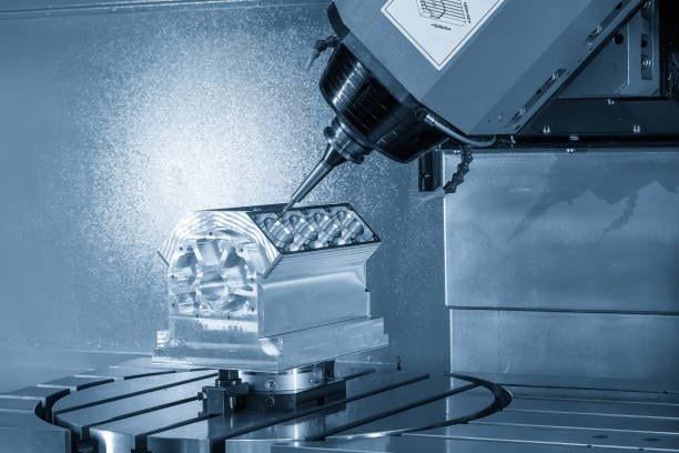
1. Design for CNC Milling
CNC milling is a machining method whereby a desired shape is obtained by fast material removal from raw materials using round cutters. Models of CNC milling machines range in design from 3-axis to 12-axis systems.
1.1 Commonly Available Cutting Tools
When designing CNC parts, give common tools like end mill cutters some thought. Standard tool sizes help to lower lead times and expenses by their simplicity. Consider standard radii for design to help to avoid complications and higher costs.
1.2 Avoid Sharp Internal Corners
With a milling tool, sharp internal corners are not easily attained since the cutting tool is round. Make sure the radii of your corners surpass those of the cutter used. The cutting tool should ideally have a twice the radius it generates internal vertical edges. Filets are also crucial where sloped or drafted surfaces cross vertical walls or sharp edges to guarantee a seamless finish.
1.3 Avoid Deep Narrow Slots
Many times, long cutting tools vibrate and deflect, which produces poor surface finish. For best findings:
- Plastic: Depth shouldn’t be more than fifteen times the tool’s diameter.
- Aluminum: Depth shouldn’t be more than 10 times the tool’s diameter.
- Depth should not be more than five times the tool’s width.
For instance, the depth should not be more than 2.75″ when cutting steel with a 0.5″ end mill that is 0.55″ wide.
1.4 Design with the Largest Possible Internal Radii
Greater material removal speed by larger cutters speeds down machining time and costs. Steer clear of radii less than 0.8mm and maximize your internal radii. Results benefit from somewhat exceeding the endmill radius; for better finishes, choose a 0.130″ radius rather than 0.125″.
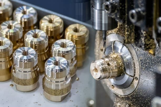
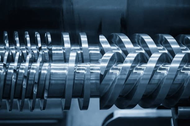
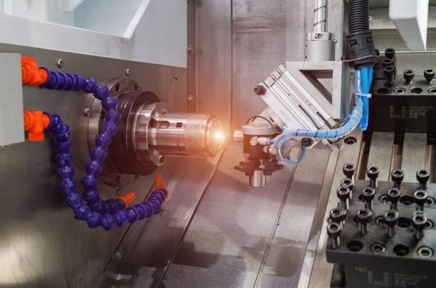
2. Design for CNC Turning
On a lathe, CNC turning generates cylindrical geometry and axial symmetry parts. Tightest tolerances and improved surface finish are guaranteed by this process.
2.1 Avoid Sharp Internal and External Corners
CNC-turned parts should be designed with sharp corners avoided. Including a radius into internal corners or slanted steep sidewalls guarantees the tool stays away from more surface area. Simplicity in design and less procedures increase efficiency.
2.2 Avoid Long, Thin Parts
Long, thin sections can chatter against the tool and spin unevenly. If a long component is required, leave free end space for a center drill to preserve stability. Generally speaking, keep your length to—diameter ratio 8:1 or less.
2.3 Avoid Thin Walls
Too much material removal lowers rigidity and increases the difficulty of achieving strict tolerances. Keep turned part wall thickness above 0.02 inches for more stability.
2.4 Feature Symmetry
Usually, CNC turning parts keep symmetry around the turning axis. Asymmetrical features could call for more sophisticated machining techniques. Maintaining simplicity and accuracy, include steps, tapers, chamfers, and curves. Save some degree of symmetry to ease the manufacturing process, if asymmetrical elements are required.
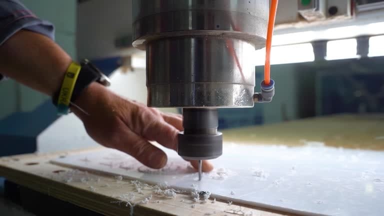
3. Design for CNC Drilling
Workpiece precision holes are made by CNC drilling. Conical tips in drills let them effectively cut through materials.
3.1 Appropriate Hole Depth
To preserve tool stiffness and lower breakage risks, never drill deeper than 12 times the closest bit diameter. Deeper holes could call for either drilling from both sides or widening the hole diameter. This calls for more machining configurations, so raising expenses.
3.2 Avoid Partial Holes
Drills tips may wander in partial holes. Should only a portion of a hole be needed, orient the drill axis on a solid block of material to increase stability.
3.3 Keep Drill Axis Perpendicular to the Surface
Maintaining a drill axis perpendicular helps to stop tip wandering. Two good ways to accomplish this are machining a flat-bottomed pocket or beginning with a pilot hole.
3.4 Avoid Drilling Through Cavities
Carefully choose where to drill holes to prevent already existing cavities. If a drilled hole has to cross a cavity, make sure its central axis runs in the same direction for maximum stability.
Best Practices in Machining Design
1. Incorporate Design for Manufacturability (DFM)
DFM ideas guarantee designs are best fit for effective manufacturing. To help to minimize machining difficulties, this entails standardizing features, avoiding sharp internal corners, and reducing complicated geometries.
2. Select the Right Machining Process
Selection of the suitable machining technique directly affects efficiency and accuracy. Typical machining techniques consist of:
- Milling: Perfect for creating intricate forms and finely detailed features is milling. Often found in dies, molds, and manufacturing of automotive components.
- Turning: Turning is appropriate for cylindrical parts including fasteners, rods, and bearings.
- Drilling: Drilling is used precisely to create holes in plastic and metal parts.
- Grinding: For parts with tight tolerance, grinding produces high surface finish and dimensional accuracy.
3. Minimize Material Waste
Using materials well lowers environmental impact and costs. Methods for reducing waste include strategic cutting angles, effective tool paths, and nesting.
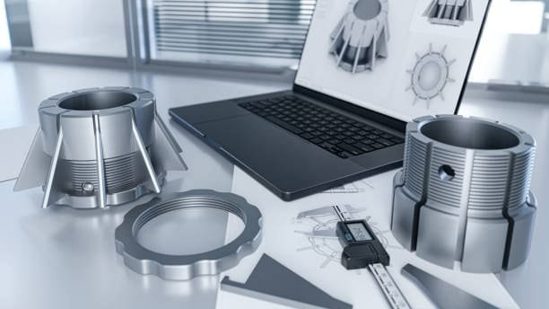
4. Embrace Computer-Aided Design (CAD) and Computer-Aided Manufacturing (CAM)

While CAM tools convert designs into machine instructions, CAD programs let designers create exact digital models. By means of CAD/CAM guarantees correct part production and enhanced efficiency.
5. Test Prototypes Before Full Production
Before committing to full-scale manufacturing, prototyping lets designers spot mistakes and improve their ideas. Excellent quick prototyping techniques are CNC machining or 3D printing.
Design Restrictions for CNC Machining
Though not all designs are achievable, the CNC machining process is flexible. You should be aware of certain limitations and restrictions to guarantee seamless machining. Two main CNC design limitations are:
Tool Geometry
The cutting lengths of most CNC cutting tools are rather short. Furthermore all of them have cylindrical forms and geometries. These cutting tools translate their cylindrical geometry to the workpiece when materials are taken off of it. This is the reason that, independent of the limited cutting length and tool size, the internal corners of a workpiece always have a radius.
Tool Access
Working on a workpiece with a significant depth-to—-width ratio starts a serious issue regarding tool access. CNC machines cut by using the cutting tools on the workpiece from above, thus this issue results.
Stated differently, machining a workpiece inaccessible from the top angle would prove challenging. Undercut machining for CNC machined parts is the one exception to this rule.
One approach to minimize this tool access difficulty is aligning the features of your part or component to one of the six main directions. Moreover, using a five-axis design for CNC machining with a great workpiece holding capacity releases tool access from limitations.
CNC Machining Design Guidelines
No set of guidelines is usually accepted in the CNC machining environment. This is mostly because the sector and the tools applied are always changing. Still, some best practices and advice will help to guarantee that your design quality stays excellent. These pointers consist of:
1. Internal Edges
Creating inner edges should have the vertical corner radius at least one-third of the cavity depth. If you follow the recommended internal corner radius radii, you can use a diameter tool with the advised cavity depth.
Slightly above the recommended value, corner radii enable you to cut along a circular path rather than a 90-degree angle, so generating a surface finish with a higher degree of quality. If you need a 90-degree angle instead, it’s advised to use a T-bone undercut instead of lowering the corner radius.
2. Holes
Machinists might make holes using end mill tools or drill bits. When deciding on the hole diameters in your design, it is advisable to follow standard drill bit sizes—measured in either metric or imperial units.
Technically, any dimension bigger than one millimeter is possible. Reamers and boring tools allow machine operators to finish holes requiring exact tolerances. For holes smaller than 20 millimeters and needing great accuracy, a standard diameter ball end mill part is ideal.
Four times the nominal diameter is the maximum suggested depth for any hole when designing parts for CNC machining; but, 40 times this amount is feasible. Usually, the nominal diamension is ten times the ratio.
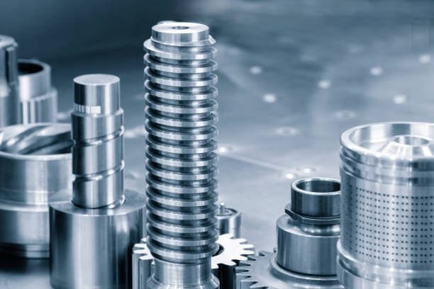
3. Threads
While M2 is the minimum thread size used in CNC-machined products, M6 or above is typically best. Through CNC threading tools and machines to cut threads as small as M6, machinists can reduce the risk of tap breakage.
The advised length for threaded holes is three times the normal; the minimum thread length should be 1.5 times the nominal diameter. You have to add an unthreaded length at the bottom of the hole 1.5 times the nominal diameter for any thread smaller than M6. For threads larger than M6, threading the hole all around its length is ideal.
4. Cavities and Pockets
The industry-recommended cavity depth on any design is four times its width since end mill tools restrict their cutting length. Greater chip evacuation, tool deflection, and vibration would follow from a smaller depth-to—width ratio.
Does your CNC design call for greater depths? Using a variable cavity depth and a specific tool will help one overcome this difficulty.
5. Small or Raised Text
You might have to mark sections using company names or part numbers. While adding text looks great in custom CNC design, processing it takes time. Usually better is electrochemical etching or laser marking.
Common Challenges in Machining Design
1. Material Deformation
Heat and cutting pressures in machining can induce material deformation. By changing cutting speeds, choosing suitable coolants, and structurally reinforcing components, designers can help to offset this.
2. Tool Wear and Breakage
Unaccuracies and downtime resulting from excessive tool wear Choosing premium tools, adjusting cutting settings, and doing regular maintenance help to lower this risk.
3. Maintaining Tight Tolerances
Precision in complicated parts calls for exact machine calibration, experienced operators, specialty tools and best tool paths.
4. Chip Evacuation
Particularly when machining deep holes or pockets, good chip control is absolutely vital. Tool damage and surface flaws can follow from poor chip evacuation. Coolant systems and proper tool geometries help to increase chip removal.
Future Trends in Machining Design
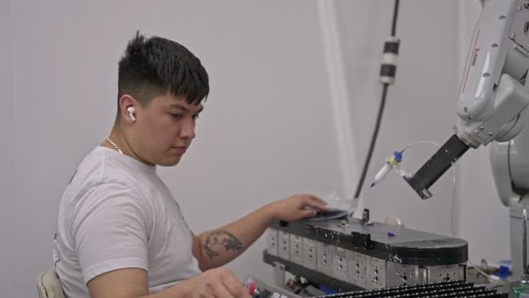
1. Automation and Robotics
Commonly used automated machining systems are improving output and lowering mistakes by means of their simplicity. Additionally becoming popular for helping human operators complete machining jobs are collaborative robots, or cobots.
2. AI-Powered Optimization
By analyzing data, AI-driven algorithms propose best machining techniques, so lowering costs and raising efficiency.
3. Advanced Materials
Stronger, lighter materials are forcing machining design to create creative ideas for better manufacturing capability. Developed to effectively handle these advanced materials are new cutting tools and coatings.
4. Sustainable Machining Practices
Emphasizing low waste and energy-efficient techniques, environmentally friendly machining solutions are becoming more and more appealing. Industry standards are developing from techniques including energy-efficient machine tools, recyclable coolants, and dry machining.
Conclusion
Modern manufacturing depends mostly on machining design to guarantee exact, functional, and reasonably priced products. Engineers can maximize product quality and reduce manufacturing costs by knowing basic design concepts, selecting appropriate materials, and using best practices machine shops. Adopting cutting-edge technologies like CAD/CAM and automation will help machining efficiency to be raised by further streamlining of operations.
Your parts’ quality and efficiency will be much improved by knowing CNC machining design limitations and applying sensible advice. Your CNC machined components will satisfy the highest standards if you consider tool geometry, tool access, design best practices for internal edges, holes, threads blind holes, cavities, and text.