Screw threads come in different shapes that determined by their angle and sizes. This article introduces knuckle thread with its form, uses, angle, standard, drawing, and dimensions chart specified by DIN 405 and DIN 20400.
What Is a Knuckle Thread?
The Knuckle thread, also called round thread or RD thread, is a special type of screw thread form known for their smooth, rounded shape. Unlike most threads that have sharp edges, knuckle threads have big, curved crests and roots. This unique design creates plenty of space between the thread parts, which helps dirt, dust, and other debris move out easily without getting stuck. Because of this, knuckle threads can resist damage and stay clean, even in tough, dirty environments.
In manufacturing, knuckle threads can be made to precise standards using both metric and imperial units. They can be single-start (one thread spiral) or multi-start (several spirals), depending on the need. Their design makes them more durable than other threads since there are no sharp edges to wear down or break.
Features of Knuckle Thread Form/Profile
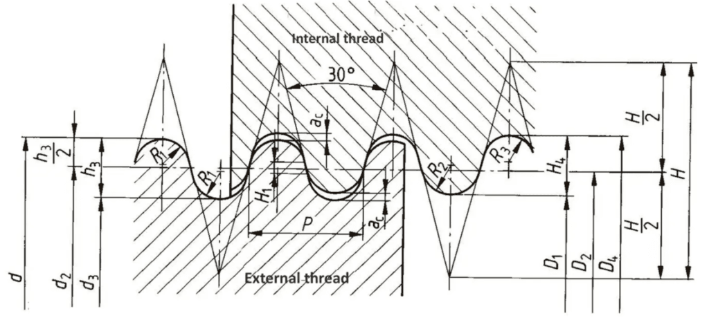
The knuckle thread profile is a modified version of the square thread, where the sharp corners of the square thread are rounded off to form a completely rounded shape, either half circular or fully circular. This rounded shape creates smooth crests and roots, reducing stress concentration and improving durability. The standard dimensions for a knuckle thread include the pitch (distance between two crests), a thread depth equal to half the pitch (0.5p), and a radius for the rounded crests and roots equal to one-quarter of the pitch (0.25p).
Knuckle Thread Diagram & Drawing
How to Draw a Knuckle Thread?
1. Draw three parallel horizontal lines spaced at 0.25 times the pitch (0.25p) apart; these represent the crest line, the center line, and the root line.
2. Mark points along the center line at intervals equal to the full pitch (p); these points will serve as centers for the semicircles.
3. From each center point on the center line, draw a semicircle with a radius of 0.25p extending upward to form the crest portion.
4. From the next center point, draw a semicircle with the same radius (0.25p) extending downward to form the root portion.
5. Alternate drawing upper and lower semicircles along the center line, connecting the crests and roots smoothly.
6. Draw the pitch dimension line to show the distance between two consecutive crests.
7. Label the depth of the thread as half the pitch (0.5p), which is the distance from the crest line to the root line.
8. Mark the radius of the rounded crests and roots as 0.25p.
9. Use a dark pencil or pen to outline the semicircular crests and roots clearly to highlight the thread profile.
10. Add a centerline and dimension lines, using chain lines to indicate the centers of the semicircles and the pitch spacing.
11. Shade the cross-section with hatching lines spaced about 2 mm apart at a 45-degree angle to indicate the material.
12. Finally, label the drawing as a “Knuckle Thread Profile” and add a dimension table listing pitch, depth, and radius values for clarity.
Knuckle Thread Standard and Angle
Knuckle thread dimensions are standardized by several important organizations, each with its own specific rules for designation, diameter, pitch, TPI, and other specifications. Most common knuckle thread specifications are DIN 405 and DIN 20400, both of them apply a flank angle of 30°.
- DIN 405: A German standard defines knuckle threads with a flat 30-degree flank angle, using inch-based pitches and covering diameters from 8 mm up to 200 mm.
- DIN 20400: A newer German standard uses metric pitches and extends the size range from 10 mm to 300 mm in diameter. In these DIN threads, the crests and roots are rounded with a radius just under one-quarter of the thread pitch, and about one-third of each thread flank is flat, creating a smooth yet strong profile.
- API: In the United States, the American Petroleum Institute (API) specification 5B covers a “round thread” mainly for tubing, commonly called “8 round” or “8rd,” meaning 8 threads per inch, with an additional 10 threads per inch option. The API round threads differ from DIN threads by having a 60-degree flank angle and smaller crest and root rounding radii, about one-sixth of the thread pitch, making them closer in shape to standard ISO threads. Additionally, API threads taper, narrowing by 3/4 inch in diameter for every foot of length.
Beyond these standards, many knuckle threads are custom-made to fit special machines or jobs, and knuckle thread forms are flexible depending on the needs of the industry or application.
What Are Knuckle Threads Used For?
Knuckle threads are used in many industries because their rounded shape helps prevent dirt and debris from causing problems, making them very reliable in tough conditions. In oilfields, they create leak-free connections that hold up well even when exposed to dirt and rough handling. European cars, like some Porsche and BMW models, use knuckle threads for their tow eyes, the special threaded holes where towing hooks attach, because the threads are strong and fit securely. These threads also protect softer materials, such as plastic nuts in linear actuators, by reducing wear when metal parts move against them. Firefighting respirators use knuckle threads to connect metal and rubber parts safely. Knuckle threads are found in underground mining hoists, train clutch and brake screws, and large valves, where their smooth, rounded design resists damage from dirt and heavy forces.
RD Knuckle Thread Dimensions
Note (DIN 405 vs DIN 20400):
DIN 405 is different from DIN 20400 in the way they measure thread pitch. DIN 405 uses a mix of metric nominal diameters but measures pitch in threads per inch (TPI), which is an imperial unit. In contrast, DIN 20400 fully adopts the metric system, using metric nominal diameters along with metric pitch measurements. This makes DIN 20400 easier to work with in countries and industries that rely entirely on metric units, and it is a simple way to tell the two standards apart.
In addition, DIN 405 offers 63 designated thread sizes, ranging from 8 mm to 200 mm, divided into two groups: Series 1, which has 40 preferred sizes, and Series 2, which has 23 sizes that are generally discouraged. On the other hand, DIN 20400 has fewer total sizes,47 in all, but it covers a wider range of diameters, from 10 mm up to 300 mm. This means DIN 20400 is better suited for larger applications compared to DIN 405.
The pitch range also varies significantly between the two standards. DIN 405 threads have a more limited pitch range, from 2.54 mm (which equals 10 threads per inch) up to 6.35 mm (4 threads per inch). DIN 20400, however, increases pitch steadily as the diameter grows, offering pitches from 3 mm all the way up to 16 mm. This allows DIN 20400 threads to be designed for heavier-duty uses where larger pitches are needed for strength and stability.
Although both DIN 405 and DIN 20400 share the same 30-degree thread flank angle, their thread root and crest shapes differ. In DIN 405, both the root and crest have a large, smooth, full-radius curve, giving them a very rounded profile. DIN 20400 keeps a large radius for the crest but changes the root design by using two smaller radii that create a flat bottom at the thread root. This subtle difference affects how the thread handles stress and wear during use.
DIN 20400 Metric Knuckle Screw Thread Chart in MM (External)
DIN 20400 Metric Knuckle Screw Thread Chart in MM (Internal)
DIN 405 Knuckle Screw Thread Chart in MM (External)
| Thread Designation | TPI* | Pitch | 6h Major Diameters | 7h Pitch Diameters | 7h Minor Diameters | |||
| Max | Min | Max | Min | Max | Min | |||
| Rd 8 x 1/10 | 10 | 2.540 | 8.000 | 7.665 | 6.730 | 6.530 | 5.460 | 5.210 |
| Rd 9 x 1/10 | 10 | 2.540 | 9.000 | 8.665 | 7.730 | 7.530 | 6.460 | 6.210 |
| Rd 10 x 1/10 | 10 | 2.540 | 10.000 | 9.665 | 8.730 | 8.530 | 7.460 | 7.210 |
| Rd 11 x 1/10 | 10 | 2.540 | 11.000 | 10.665 | 9.730 | 9.530 | 8.460 | 8.210 |
| Rd 12 x 1/10 | 10 | 2.540 | 12.000 | 11.665 | 10.730 | 10.530 | 9.460 | 9.210 |
| Rd 14 x 1/8 | 8 | 3.175 | 14.000 | 13.625 | 12.730 | 12.494 | 10.825 | 10.525 |
| Rd 16 x 1/8 | 8 | 3.175 | 16.000 | 15.625 | 14.412 | 14.176 | 12.825 | 12.525 |
| Rd 18 x 1/8 | 8 | 3.175 | 18.000 | 17.625 | 16.412 | 16.176 | 14.825 | 14.525 |
| Rd 20 x 1/8 | 8 | 3.175 | 20.000 | 19.625 | 18.412 | 18.176 | 16.825 | 16.525 |
| Rd 22 x 1/8 | 8 | 3.175 | 22.000 | 21.625 | 20.412 | 20.176 | 18.825 | 18.525 |
| Rd 24 x 1/8 | 8 | 3.175 | 24.000 | 23.625 | 22.412 | 22.176 | 20.825 | 20.525 |
| Rd 26 x 1/8 | 8 | 3.175 | 26.000 | 25.625 | 24.412 | 24.176 | 22.825 | 22.525 |
| Rd 28 x 1/8 | 8 | 3.175 | 28.000 | 27.625 | 26.412 | 26.176 | 25.825 | 25.525 |
| Rd 30 x 1/8 | 8 | 3.175 | 30.000 | 29.625 | 28.412 | 28.176 | 26.825 | 26.525 |
| Rd 32 x 1/8 | 8 | 3.175 | 32.000 | 31.625 | 30.412 | 30.176 | 28.825 | 28.525 |
| Rd 34 x 1/8 * | 8 | 3.175 | 34.000 | 33.625 | 32.412 | 32.176 | 30.825 | 30.525 |
| Rd 36 x 1/8 | 8 | 3.175 | 36.000 | 35.625 | 34.412 | 34.176 | 32.825 | 32.525 |
| Rd 38 x 1/8 * | 8 | 3.175 | 38.000 | 37.625 | 36.412 | 36.176 | 34.825 | 34.525 |
| Rd 40 x 1/6 | 6 | 4.233 | 40.000 | 39.525 | 37.883 | 37.583 | 35.767 | 35.392 |
| Rd 42 x 1/6 * | 6 | 4.233 | 42.000 | 41.525 | 39.883 | 39.583 | 37.767 | 37.392 |
| Rd 44 x 1/6 | 6 | 4.233 | 44.000 | 43.525 | 41.883 | 41.583 | 39.767 | 39.392 |
| Rd 46 x 1/6 * | 6 | 4.233 | 46.000 | 45.525 | 43.883 | 43.583 | 41.767 | 41.392 |
| Rd 48 x 1/6 | 6 | 4.233 | 48.000 | 47.525 | 45.883 | 45.583 | 43.767 | 43.392 |
| Rd 50 x 1/6 * | 6 | 4.233 | 50.000 | 49.525 | 47.883 | 47.583 | 45.767 | 45.392 |
| Rd 52 x 1/6 | 6 | 4.233 | 52.000 | 51.525 | 49.883 | 49.583 | 47.767 | 47.392 |
| Rd 55 x 1/6 | 6 | 4.233 | 55.000 | 54.525 | 52.883 | 52.583 | 50.767 | 50.392 |
| Rd 58 x 1/6 * | 6 | 4.233 | 58.000 | 57.525 | 55.883 | 55.583 | 53.767 | 53.392 |
| Rd 60 x 1/6 | 6 | 4.233 | 60.000 | 59.525 | 57.883 | 57.583 | 55.767 | 55.392 |
| Rd 62 x 1/6 * | 6 | 4.233 | 62.000 | 61.525 | 59.883 | 59.583 | 57.767 | 57.392 |
| Rd 65 x 1/6 | 6 | 4.233 | 65.000 | 64.525 | 62.883 | 62.583 | 60.767 | 60.392 |
| Rd 68 x 1/6 * | 6 | 4.233 | 68.000 | 67.525 | 65.883 | 65.583 | 63.767 | 63.392 |
| Rd 70 x 1/6 | 6 | 4.233 | 70.000 | 69.525 | 67.883 | 67.583 | 65.767 | 65.392 |
| Rd 72 x 1/6 * | 6 | 4.233 | 72.000 | 71.525 | 69.883 | 69.583 | 67.767 | 67.392 |
| Rd 75 x 1/6 | 6 | 4.233 | 75.000 | 74.525 | 72.883 | 72.583 | 70.767 | 70.392 |
| Rd 78 x 1/6 * | 6 | 4.233 | 78.000 | 77.525 | 75.883 | 75.583 | 73.767 | 73.392 |
| Rd 80 x 1/6 | 6 | 4.233 | 80.000 | 79.525 | 77.883 | 77.583 | 75.767 | 75.392 |
| Rd 82 x 1/6 * | 6 | 4.233 | 82.000 | 81.525 | 79.883 | 79.583 | 77.767 | 77.392 |
| Rd 85 x 1/6 | 6 | 4.233 | 85.000 | 84.525 | 82.883 | 82.583 | 80.767 | 80.392 |
| Rd 88 x 1/6 * | 6 | 4.233 | 88.000 | 87.525 | 85.883 | 85.583 | 83.767 | 83.392 |
| Rd 90 x 1/6 | 6 | 4.233 | 90.000 | 89.525 | 87.883 | 87.583 | 85.767 | 85.392 |
| Rd 92 x 1/6 * | 6 | 4.233 | 92.000 | 91.525 | 89.883 | 89.583 | 87.767 | 87.392 |
| Rd 95 x 1/6 | 6 | 4.233 | 95.000 | 94.525 | 92.883 | 92.583 | 90.767 | 90.392 |
| Rd 98 x 1/6 * | 6 | 4.233 | 98.000 | 97.525 | 95.883 | 95.583 | 93.767 | 93.392 |
| Rd 100 x 1/6 | 6 | 4.233 | 100.000 | 99.525 | 97.883 | 97.583 | 95.767 | 95.392 |
| Rd 105 x 1/4 * | 4 | 6.350 | 105.000 | 104.370 | 101.825 | 101.425 | 98.650 | 98.150 |
| Rd 110 x 1/4 | 4 | 6.350 | 110.000 | 109.370 | 106.825 | 106.425 | 103.650 | 103.150 |
| Rd 115 x 1/4 * | 4 | 6.350 | 115.000 | 114.370 | 111.825 | 111.425 | 108.650 | 108.150 |
| Rd 120 x 1/4 | 4 | 6.350 | 120.000 | 119.370 | 116.825 | 116.425 | 113.650 | 113.150 |
| Rd 125 x 1/4 * | 4 | 6.350 | 125.000 | 124.370 | 121.825 | 121.425 | 118.650 | 118.150 |
| Rd 130 x 1/4 | 4 | 6.350 | 130.000 | 129.370 | 126.825 | 126.425 | 123.650 | 123.150 |
| Rd 135 x 1/4 * | 4 | 6.350 | 135.000 | 134.370 | 121.825 | 121.425 | 128.650 | 128.150 |
| Rd 140 x 1/4 | 4 | 6.350 | 140.000 | 139.370 | 136.825 | 136.425 | 133.650 | 133.150 |
| Rd 145 x 1/4 * | 4 | 6.350 | 145.000 | 144.370 | 141.825 | 141.425 | 138.650 | 138.150 |
| Rd 150 x 1/4 | 4 | 6.350 | 150.000 | 149.370 | 146.825 | 146.425 | 143.650 | 143.150 |
| Rd 155 x 1/4 * | 4 | 6.350 | 155.000 | 154.370 | 151.825 | 151.425 | 148.650 | 148.150 |
| Rd 160 x 1/4 | 4 | 6.350 | 160.000 | 159.370 | 156.825 | 156.425 | 153.650 | 153.150 |
| Rd 165 x 1/4 * | 4 | 6.350 | 165.000 | 164.370 | 161.825 | 161.425 | 158.650 | 158.150 |
| Rd 170 x 1/4 | 4 | 6.350 | 170.000 | 169.370 | 166.825 | 166.425 | 163.650 | 163.150 |
| Rd 175 x 1/4 * | 4 | 6.350 | 175.000 | 174.370 | 171.825 | 171.425 | 168.650 | 168.150 |
| Rd 180 x 1/4 | 4 | 6.350 | 180.000 | 179.370 | 176.825 | 176.425 | 173.650 | 173.150 |
| Rd 185 x 1/4 * | 4 | 6.350 | 185.000 | 184.370 | 181.825 | 181.425 | 178.650 | 178.150 |
| Rd 190 x 1/4 | 4 | 6.350 | 190.000 | 189.370 | 186.825 | 186.425 | 183.650 | 183.150 |
| Rd 195 x 1/4 * | 4 | 6.350 | 195.000 | 194.370 | 191.825 | 191.425 | 188.650 | 188.150 |
| Rd 200 x 1/4 | 4 | 6.350 | 200.000 | 199.370 | 196.825 | 196.425 | 193.650 | 193.150 |
DIN 405 Knuckle Screw Thread Chart in MM (Internal)
| Thread Designation | TPI* | Pitch | Major Diameter | 7H Pitch Diameters | 6H Minor Diameters | ||
| Min | Min | Max | Min | Max | |||
| Rd 8 x 1/10 | 10 | 2.540 | 8.254 | 6.730 | 6.995 | 5.714 | 6.164 |
| Rd 9 x 1/10 | 10 | 2.540 | 9.254 | 7.730 | 7.995 | 6.714 | 7.164 |
| Rd 10 x 1/10 | 10 | 2.540 | 1.025 | 8.730 | 8.995 | 7.714 | 8.164 |
| Rd 11 x 1/10 | 10 | 2.540 | 11.254 | 9.730 | 9.995 | 8.714 | 9.164 |
| Rd 12 x 1/10 | 10 | 2.540 | 12.254 | 10.730 | 10.995 | 9.714 | 10.164 |
| Rd 14 x 1/8 | 8 | 3.175 | 14.318 | 12.730 | 13.045 | 11.142 | 11.672 |
| Rd 16 x 1/8 | 8 | 3.175 | 16.318 | 14.412 | 14.727 | 13.142 | 13.672 |
| Rd 18 x 1/8 | 8 | 3.175 | 18.318 | 16.412 | 16.727 | 15.142 | 15.672 |
| Rd 20 x 1/8 | 8 | 3.175 | 20.318 | 18.412 | 18.727 | 17.142 | 17.672 |
| Rd 22 x 1/8 | 8 | 3.175 | 22.318 | 20.412 | 20.727 | 19.142 | 19.672 |
| Rd 24 x 1/8 | 8 | 3.175 | 24.318 | 22.412 | 22.727 | 21.142 | 21.672 |
| Rd 26 x 1/8 | 8 | 3.175 | 26.318 | 24.412 | 24.727 | 23.142 | 23.672 |
| Rd 28 x 1/8 | 8 | 3.175 | 28.318 | 26.412 | 26.727 | 25.142 | 25.672 |
| Rd 30 x 1/8 | 8 | 3.175 | 30.318 | 28.412 | 28.727 | 27.142 | 27.672 |
| Rd 32 x 1/8 | 8 | 3.175 | 32.318 | 30.412 | 30.727 | 29.142 | 29.672 |
| Rd 34 x 1/8 * | 8 | 3.175 | 34.318 | 32.412 | 32.727 | 31.142 | 31.672 |
| Rd 36 x 1/8 | 8 | 3.175 | 36.318 | 34.412 | 34.727 | 33.142 | 33.672 |
| Rd 38 x 1/8 * | 8 | 3.175 | 38.318 | 36.412 | 36.727 | 35.142 | 35.672 |
| Rd 40 x 1/6 | 6 | 4.233 | 40.423 | 37.883 | 38.283 | 36.190 | 36.820 |
| Rd 42 x 1/6 * | 6 | 4.233 | 42.423 | 39.883 | 40.283 | 38.190 | 38.820 |
| Rd 44 x 1/6 | 6 | 4.233 | 44.423 | 41.883 | 42.283 | 40.190 | 40.820 |
| Rd 46 x 1/6 * | 6 | 4.233 | 46.423 | 43.883 | 44.283 | 42.190 | 42.820 |
| Rd 48 x 1/6 | 6 | 4.233 | 48.423 | 45.883 | 46.283 | 44.190 | 44.820 |
| Rd 50 x 1/6 * | 6 | 4.233 | 50.423 | 47.883 | 48.283 | 46.190 | 46.820 |
| Rd 52 x 1/6 | 6 | 4.233 | 52.423 | 49.883 | 50.283 | 48.190 | 48.820 |
| Rd 55 x 1/6 | 6 | 4.233 | 55.423 | 52.883 | 53.283 | 5.190 | 5.820 |
| Rd 58 x 1/6 * | 6 | 4.233 | 58.423 | 55.883 | 56.283 | 54.190 | 54.820 |
| Rd 60 x 1/6 | 6 | 4.233 | 60.423 | 57.883 | 58.283 | 56.190 | 56.820 |
| Rd 62 x 1/6 * | 6 | 4.233 | 62.423 | 59.883 | 60.283 | 58.190 | 58.820 |
| Rd 65 x 1/6 | 6 | 4.233 | 65.423 | 62.883 | 63.283 | 61.190 | 61.820 |
| Rd 68 x 1/6 * | 6 | 4.233 | 68.423 | 65.883 | 66.283 | 64.190 | 64.820 |
| Rd 70 x 1/6 | 6 | 4.233 | 70.423 | 67.883 | 68.283 | 66.190 | 66.820 |
| Rd 72 x 1/6 * | 6 | 4.233 | 72.423 | 69.883 | 70.283 | 68.190 | 68.820 |
| Rd 75 x 1/6 | 6 | 4.233 | 75.423 | 72.883 | 73.283 | 71.190 | 71.820 |
| Rd 78 x 1/6 * | 6 | 4.233 | 78.423 | 75.883 | 76.283 | 74.190 | 74.820 |
| Rd 80 x 1/6 | 6 | 4.233 | 80.423 | 77.883 | 78.283 | 76.190 | 76.820 |
| Rd 82 x 1/6 * | 6 | 4.233 | 82.423 | 79.883 | 80.283 | 78.190 | 78.820 |
| Rd 85 x 1/6 | 6 | 4.233 | 85.423 | 82.883 | 83.283 | 81.190 | 81.820 |
| Rd 88 x 1/6 * | 6 | 4.233 | 88.423 | 85.883 | 86.283 | 84.190 | 84.820 |
| Rd 90 x 1/6 | 6 | 4.233 | 90.423 | 87.883 | 88.283 | 86.190 | 86.820 |
| Rd 92 x 1/6 * | 6 | 4.233 | 92.423 | 89.883 | 90.283 | 88.190 | 88.820 |
| Rd 95 x 1/6 | 6 | 4.233 | 95.423 | 92.883 | 93.283 | 91.190 | 91.820 |
| Rd 98 x 1/6 * | 6 | 4.233 | 98.423 | 95.883 | 96.283 | 94.190 | 94.820 |
| Rd 100 x 1/6 | 6 | 4.233 | 100.423 | 97.883 | 98.283 | 96.190 | 96.820 |
| Rd 105 x 1/4 * | 4 | 6.350 | 105.635 | 101.825 | 102.355 | 99.285 | 100.115 |
| Rd 110 x 1/4 | 4 | 6.350 | 110.635 | 106.825 | 107.355 | 104.285 | 105.115 |
| Rd 115 x 1/4 * | 4 | 6.350 | 115.635 | 111.825 | 112.355 | 109.285 | 110.115 |
| Rd 120 x 1/4 | 4 | 6.350 | 120.635 | 116.825 | 117.355 | 114.285 | 115.115 |
| Rd 125 x 1/4 * | 4 | 6.350 | 125.635 | 121.825 | 122.355 | 119.285 | 120.115 |
| Rd 130 x 1/4 | 4 | 6.350 | 130.635 | 126.825 | 127.355 | 124.285 | 125.115 |
| Rd 135 x 1/4 * | 4 | 6.350 | 135.635 | 121.825 | 122.355 | 129.285 | 130.115 |
| Rd 140 x 1/4 | 4 | 6.350 | 140.635 | 136.825 | 137.355 | 134.285 | 135.115 |
| Rd 145 x 1/4 * | 4 | 6.350 | 145.635 | 141.825 | 142.355 | 139.285 | 140.115 |
| Rd 150 x 1/4 | 4 | 6.350 | 150.635 | 146.825 | 147.355 | 114.285 | 115.115 |
| Rd 155 x 1/4 * | 4 | 6.350 | 155.635 | 151.825 | 152.355 | 149.285 | 150.115 |
| Rd 160 x 1/4 | 4 | 6.350 | 160.635 | 156.825 | 157.355 | 154.285 | 155.115 |
| Rd 165 x 1/4 * | 4 | 6.350 | 165.635 | 161.825 | 162.355 | 159.285 | 160.115 |
| Rd 170 x 1/4 | 4 | 6.350 | 170.635 | 166.825 | 167.355 | 164.285 | 165.115 |
| Rd 175 x 1/4 * | 4 | 6.350 | 175.635 | 171.825 | 172.355 | 159.285 | 160.115 |
| Rd 180 x 1/4 | 4 | 6.350 | 180.635 | 176.825 | 177.355 | 174.285 | 175.115 |
| Rd 185 x 1/4 * | 4 | 6.350 | 185.635 | 181.825 | 182.355 | 179.285 | 180.115 |
| Rd 190 x 1/4 | 4 | 6.350 | 190.635 | 186.825 | 187.355 | 184.285 | 185.115 |
| Rd 195 x 1/4 * | 4 | 6.350 | 195.635 | 191.825 | 192.355 | 189.285 | 190.115 |
| Rd 200 x 1/4 | 4 | 6.350 | 200.635 | 196.825 | 197.355 | 194.285 | 195.115 |
| Marked with * are designated as Series-2 sizes; avoid using these in new designs. | |||||||