Check out the list of the 22 most popular common injection molding defects encountered in various manufacturing processes, the causes leading to them, and effective methods of prevention. Find out how to remove flow lines, sink marks, warping and other issues, which affect the quality of your manufacturing process.
Understanding Injection Molding Defects in Manufacturing
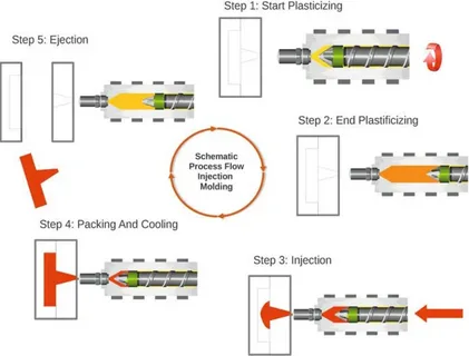
Injection molding has been found to be one of the most effective production processes of manufacturing high volume parts of plastic. Nevertheless, the multidimensionality of this process opens a wide range of variables that create a possibility of some defects resulting in inadequate injection pressure quality of the product and production overheads. These defects are important to know about by the manufacturers, engineers and quality control staff who aim at manufacturing parts of high standard continuously.
The Critical Impact of Injection Molding Defects on Production
The injection molding manufacturing defects may play a major role in production efficiency, product quality, and profitability. There are a great number of causes of injection molding problems and defects and they can be because of bad design, production process messes, quality control mishaps and so forth and so on. Such defects do not only cause the waste of materials but can also lead to material degradation, causing delays in the production that is costly, customer discontent, and safety problems.
Flow Lines: Visible Patterns on Part Surfaces
One of the most popular visual defects which appeal in the injection molding process is the flow lines. The surfaces of molded pieces show these as off-color streaks, lines or patterns. Flow lines owing to the different rates of flow of molten plastic inside the mold cavity results in an uneven rate of cooling leading to the appearance of a pattern on the surface of the flow which is not the same as the color of the base material.
Root Causes of Flow Lines in Injection Molding
Flow lines are normally due to inadequate injection speed or pressure: such that the plastic stalls or slows down when it is trying to fill a cavity. The defect is also brought about by temperature changes in the mold. On milling thermoplastic resin with various thickness of walls it results in turbulent flow patterns which are then seen as physical lines on the end product.
Preventing Flow Lines Through Process Optimization
In order to remove flow lines, manufacturers need to fasten the injection speed at which materials are injected as well as pressure so as to have a continuous flow of material. The part should be designed with consistent wall thickness in its walls. Furthermore, efficient placement of gates in thin-walled areas of the mold cavity assists in making fluid flow smooth as well as chances of occurrence of a flow line, many times, are minimized.
Sink Marks: Understanding Depression Defects
Sink marks are depressions, dents or crater like sinks which occur on thick areas of injection molded parts made from plastic. Such defects are incurred when foreign material causes the thicker portion of the part to cool more rapidly than the thinner part and the inner part hence contracts and shrinks when the outer surface has already solidified.
Why Sink Marks Develop in Thick Wall Sections
Uneven cooling of both thick and thin areas of a part is the main attribute to sink marks. As the outer material shrinks the inner material still heating up develops a solid skin, when the outer material still has not cooled as quickly as thick cuts. This difference in cooling causes internal openings that cause the surface to be sucked in resulting in the presence of the depression.
Eliminating Sink Marks Through Design Modifications
Sink marks would be avoided by implementing quality control measures and paying close attention to uniform wall thickness consistency at the design level. The most thick wall areas are reduced to facilitate even cooling. Also pressure of hold and holding time can be boosted, which enables to cram more material into the cavity in offsetting natural shrinkage upon cooling.
Surface Delamination: Layer Separation Issues
When a part separates into thin layers that can be peeled off its surface due to trapped air pockets , it is called surface delamination. This flaw affects the aestheticism and strength of the molded component. The delamination process may induce weak spots which could cause premature failure as a stress may build up or when left exposed to the environment.
Contamination Causes Behind Surface Delamination
The delamination is mostly a result of contamination in raw material or over use of mold release agents. Incompatible substances, water, or foreign components will inhibit the correct adhesion of plastic resin layers in the process of molding. Another factor that can cause inadequate adhesion of materials is overuse of the mold release agent, which in itself creates some form of barrier.
Strategies for Preventing Surface Delamination

Manufacturers ought to adopt pre-drying of the material and close contamination control practice to avoid delamination by pre-drying the material prior to molding. By consuming less mold release agent due to the optimization of mold design and ejection methods, the possible barriers to bonding can be avoided. More favourable material flow and bonding properties can be obtained by heating up the mold.
Weld Lines: Junction Defects in Complex Geometries
Knit lines (sometimes called weld lines) occur in the location that two streams of molten plastic merge, which has made it around a block, or has passed through more than one gate. The lines will look as visible seams on the part surface and correspond to regions of high injection pressure strength because of failing to completely bond the material flows involved.
Formation Mechanisms of Weld Lines
Weld lines are formed when the flow of plastics are separated by holes, pins, or other mold geometrical elements. There are not enough temperature or enough pressure during the injection process to bond as the separated flows come back together. Otherwise, they will partly solidify and fail to adhere to each other at the point of contact that leads to the formation of weld lines.
Eliminating Weld Lines Through Process Control
To eliminate weld lines, raise the temperature of the material so as to have fluidity of flows at points of re-convergence. Increased injection speeds and reducing injection pressure aid to provide correct bonding at connection points. The part designers have the option of considering materials that have low viscosity, low melting temperatures to minimize the occurrence of weld lines. The gate placement can also be strategically placed to alter the flow patterns in order to reduce the convergence problem spots.
Short Shots: Incomplete Cavity Filling
Short shots Short shots happen when the molten plastic will not completely fill the mold cavity leaving incomplete parts. Such a defect makes parts unusable, which is a major loss of material and production time. Short shots may take place in any section of the part but usually happen in thin regions or the regions furthest away form a gate.
Understanding Short Shot Root Causes
The common causes of short shots include insui vocent injection pressure, a blockage of material flow, or poor venting. Obstructed gates or small-sized gates restrict the passage of materials into the hole. The rear-pressure may balk off the filling due to entangled air. Short shot formation may also occur in high material viscosity or low mold temperature.
Solutions for Preventing Short Shots
Short shots can be prevented by improving injection pressure and fine tuning the size of the gates. Correct venting design will permit air to escape during filling process. As the molds get hot, the viscosity of the material and the flowability properties are aught. Gates and runners are well maintained on a regular basis to eliminate blockage which may limit the progress of materials.
Warping: Dimensional Distortion in Molded Parts
Warping presents itself in the form of twists/ bending or dimensional distortions on the molded parts that are unintentional. This defect not only impairs the structural integrity of part but it may inhibit the ability to assemble or operate. Warping is especially an issue in precision applications, where tolerances are very sensitive.
Thermal Stress Mechanisms Behind Warping
Warping is created by uneven internal stresses put on the metal during the cooling process as it cools. Both unbalanced cooling of the part and uniform shrinkage result in a shrinkage that is not even in all parts of the part; some areas shrink more than others. This is a differential shrinkage which causes internal stresses which distort the geometry of the part as it cools.
Preventing Warping Through Controlled Cooling
If you want to avoid warping, apply consistency in cooling the part and well designed mold of cooling channels. Constant wall thickness also ensures that the rate of cooling of the part is similar throughout the part. Slow cooling enables the internal stresses to anneal automatically, and the part is not distorted.
Jetting: Serpentine Flow Patterns
Jetting forms apparent serpentine or wavy currents on the surface of parts. Such a defect takes place when a first jet of material gets to the mold cavity and starts solidifying before the cavity is totally filled. The concentrated media form flow disturbances which take the form of observable patterns on the completed part.
Injection Pressure Effects on Jetting
Over injection pressure may lead to the propelling of material into the mold cavity in excess, forming a turbulent basis. As the first jet of the material meets the wall of the mold, it may serpentine on the surface and then be forced by other material stream. It is this whip-like movement which makes the characteristic jetting pattern.
Controlling Jetting Through Process Adjustment
Jetting can be avoided by avoiding excessive injection pressure and injecting at a lowered pressure, to induce slower cavity filling. An increase in mold and material temperatures keeps the material fluid, lowers the possibility of premature solidification. Material flow can be guided through proper gate design and location as well to reduce the occurrence of jetting.
Flash: Excess Material Beyond Part Boundaries
Flash comes in the form of thin fins; or too much material coming out of the planned part. This defect, classified among common injection mold defects, will happen when molten plastic is able to get an exit on the mold cavity dents or parting lines, clearances on the ejector pins or other crevices in the mold body. Flash calls upon more finishing work and may also be a sign of more severe mold or process problems.
Mold Clamping and Flash Formation
Inadequate clamping force provides just enough space to open the mold half-way under injection pressure and leave the mold half open to permit material to seep out. Usage or breakage of molds can also assume material escape routes. An unexpected burst of injection pressure may defeat typical mold clamped pressure and push plastic to unintended locations.
Preventing Flash Through Mold Maintenance
Consistency in maintenance of molds provides significant sealing of molds and flash avoidance. Clamping force is sufficient enough to avoid separation during Injection. When injection pressure is maintained at suitable levels, chances of the materials escaping are minimized. Fine mold design and a set draft angles and clearances reduce flash prone areas.
Burn Marks: Thermal Degradation Indicators
Burn marks are being in form of dark streaks or discoloured areas on the surface of parts which means that the plastic material is thermally degraded. These marks do not only leave scars, but can point at regions of possible strength material weakening by overheating. These burn marks are common on places where material has either too much shear heating or been exposed to too high temperatures.
Causes of Thermal Degradation in Molding
Burn marks occur due to excess material temperature, long-term stay in heated areas or high shear rate in the injection process. Small gates or runners will give frictional heating, damaging the material. Poor venting may allow still air to become compressed and heated during injection leading to local burning.
Eliminating Burn Marks Through Temperature Control
Burn marks should be prevented by optimizing the material temperature settings to reduce melt temperature in order to not exceed the overheating limits but at the same time preserve appropriate flow characteristics. Where shear heating can occur, slow down the speed of injection. Enhance the venting layout to halt air compression and heating. The possibility of degradation is avoided by frequent change of material with long residence times in heated areas.
Silver Streaking: Moisture and Volatile Contamination
Silver streaking- Silver streaking is in the form of fine silvery traces or streaks on the surface of parts. This flaw usually signifies the existence of moisture, gas pollutants or oxymoronic plastic resin. First, silver streaks may affect the finished part in terms of its appearance as well as mechanical properties.
Moisture Effects on Material Quality
The most frequent reason behind silver streaking is related to moisture contamination. Once the material with water content in it reaches the hot barrel, the water vaporizes, making steam which produces bubbles in the melted plastic. With these bubbles the typical silver effect is created when they come to the surface of the part.
Preventing Silver Streaking Through Material Preparation
Silver streaking because of moisture is avoided by proper material drying prior to processing. Make sure that you follow the instructions given by the manufacturer of the material when it comes to the drying time and temperature. Moisten materials must be stored in closed packages to avoid re absorption of the moisture. Constant care of drying equipment will result in a continuous removal of moisture.
Splay Marks: Radial Stress Patterns
Splay marks take a form of radial streaks or any fan-like distribution originating form gate points. Such marks are connected with stress concentrations or with a high film velocity, causing surface inperfections. The splay marks are more prominent on the parts that have increased requirements towards the surface quality.
Gate Design Impact on Splay Formation
Improper gate design may also result into the acceleration of the material into the mold cavity in a turbulent flow which results into stress concentration. Splay marks might be induced by the shear rate that is elevated by small gates or an ill-placed gate that brings about impingement. It is known that the shape and size of the gate affects material streams to a great extent.
Optimizing Gate Design to Prevent Splay
The correct gate-sizing is a compromise between fill time, and flow quality to avoid splay marks. Gate transitions which allow gradual changes in the flow allow reduced acceleration of the flow and reduce stress concentrations. The flow can better be divided by using multiple gates, which exerts less stress on the individual gate. The placement of the strategic gates helps in the avoidance of flow impingement into the mold walls.
Vacuum Voids: Internal Air Entrapment
The destruction of vacuum voids is in the form of internal cavities or bubbles on the part molded.These faults reduce the structural integrity and may cause premature breakage under stress.Structures Vacuum voids are especially undesirable in structural applications where internal defect will quickly extend, leading to disastrous failure.
Air Entrapment Mechanisms in Molding
Vacuum voids can arise when injected air is trapped and can not vent along typical venting means. The filling of air pockets may be entrapped during rapid injection, therefore being compressed and warmed. Effective venting design does not allow the entrapment of air which in turn forms internal gaps as it cools and may retract.
Preventing Vacuum Voids Through Venting Optimization
The correct design of venting enables entrapment of air during filling of the cavity. Vents are also positioned strategically so as to avoid formation of voids especially in areas likely to hold air. During controlled injection speed, there is less entrapment of air and sufficient filling. Vent maintenance makes it possible to get a consistent air evacuation capacity.
Brittleness: Compromised Material Properties
Brittleness is characterized by taking on decreased resistance to impact and high vulnerability to cracking or breaking. This flaw may be due to degradation, contamination or wrong processing conditions, making the plastic material vulnerable to defects injection speed and pressure
. There is a risk of unexpected failure of brittle parts operated under normal conditions and this gives rise to safety issues injection molding process parameters.
Thermal and Chemical Degradation Effects
To much processing temperature may fragment the chains of polymer and increase the toughness of materials. Material properties may also be harmed by chemical contamination, by incompatible materials, or by incompatible cleaning agents. Performance of materials reduces due to oxidation after exposure to air under high temperatures insufficient injection pressure.
Maintaining Material Properties Through Process Control
Reduce processing parameters to provide material integrity with adequate flow properties. Avoid contact by adequate material handling and storage practices injection molding material. Avoid degradation during processing by addition of proper antioxidant and stabilizers. The checks on property retention through regular material testing are carried out during the production process.
Color Variation: Consistency in Appearance
Presence of color variation manifests itself in inconsistent coloring of different parts within a production run or of a single part. This is a defect that interferes with appearance of product and may represent process variations. Invisible parts and consumer products are especially demanding on color consistency plastic injection molding.
Factors Affecting Color Consistency
The cause of variation on color may be the non-uniform mixing of the materials, change in temperature, or residence time injection molding machine. Poor dispersion of pigments or other additives will leave some parts with different colors. Color consistency may also suffer interference of old materials or left-over clean products molded plastic.
Achieving Consistent Coloration
Appropriate mixing of materials in right proportion assures a homogenous distribution of colorant within the resin. Regular temperatures of processing avoid the changes in color by heat. Contamination is avoided by frequent purging between the changes of material. The correct selection and addition of color stabilize the color through all production batches troubleshooting injection molding defects.
Dimensional Instability: Precision and Tolerance Issues
Dimensional instability may be in the form of parts made from specific molding material which fail to meet a given tolerance or tolerances which change with time. This defect may not allow assembly or operation properly and may need secondary operations to rectify the same. Such precision applications as dimensional control of precision parts, and automated assembly processes require precision dimensional control injection molding refers.
Shrinkage and Thermal Effects on Dimensions
As the part cools shrinkage is not uniform, resulting in dimensional differences across the part molten material. The thin and thick parts undergo cooling at different rates leading to a form of shrinkage of dimensions. Shrinkage may go on longer especially with semi-crystalline materials.
Controlling Dimensional Stability
Maximize cooling design by minimizing steps in temperature across the part. True process conditions lowers part-to-part dimensional change. Sizing and location of gates are proper in order to minimize stressed-induced effects that may occur on dimensions due to flow. Before final inspection dimensions can be stabilized using post-molding conditioning potential injection molding defects.
Gate Marks: Cosmetic Defects from Gate Removal
Gate marks are surface defects found where the gates were opened up the part that was molded. These stains will interfere with appearance and can necessitate such additional finishing processes as polishing. The severity of gate mark is based on gate design, removal technique and geometry of the part high melt temperature.
Gate Design Influence on Mark Formation
The size and shape of gates has a big impact on how gates will appear after removal in appearance. The bigger doors will leave more significant impressions and are necessary in case stuffing should be sufficient. The position of the gates influences the quality of the filling as well as ensuring the marks are visible on the final part.
Minimizing Gate Mark Impact
Gate design should be optimized to be able to meet the filling requirements and desired image of a mark. Significant reduction in cosmetic impact can be done by locating strategic gates in less visible locations. The removal techniques of gates are properly performed to lower surface damage. When gate marks must be removed, they can be done by secondary finishing operations.
Ejector Pin Marks: Mechanical Damage During Removal
Ejector pin ejection marks to obtain a part out of the mold is represented by circular/surface marks where the ejector pin is in contact with the part. Such marks may have purely cosmetic, and in places of critical value, or structural failure impact.
Ejector System Design Considerations
Mark formation and part removal quality is influenced by the size, position and distribution of ejector pins. Small ejector area may lead to large contact stresses, which ruined the surface of part. Incorrect care on the ejector pin might cause the scratches or gouges on the surfaces.
Optimizing Ejector Systems
The correct sizing of the ejectors pins spreads the removal forces out to reduce marking of the surface. Pin strategy does not put critical part faces and stress-concentration points. Consistent care of the ejector pins also eliminates damages on the surfaces caused by the worn-out or damaged pins. Part removal low forces are reduced through control of ejector speed.
Quality Control Strategies for Defect Prevention
Quality control cannot be considered successful without the systematic monitoring of the process parameters and the part quality during the production. Process variations can be observed in real time during cooling time so that before producing defects, they can be noticed. Statistical process control methods assist in detecting trends and avoiding quality drifts with time.
Process Monitoring and Control Systems
With advanced monitoring systems, vital aspects like temperature, pressure and time are monitored during the molding cycle. The parameters can be altered in real-time to always ensure favorable conditions are upheld through automated systems. Data logging is used to ensure past records can be used to troubleshoot (including process optimization).
Implementing Preventive Measures
With the program of preventive maintenance, maintenance of molds and equipment is maintained. Frequent training keeps operators acquainted with the methods of detecting and avoiding defects. Process variation is minimized and a high degree of consistency is obtained when using standardised procedures. The causes of defects are detected and removed by continuous improvement programs.
Advanced Troubleshooting Techniques
The systematic troubleshooting methods are applicable in finding the causes of defects in a short and effective way. Design of experiment can separate out the effects of individual parameters and optimize several variables at once. Failure analysis methods contribute to the apprehension of the defect mechanism as well as effective solution development.
Statistical Analysis for Process Improvement
The statistical techniques of process control are used in recognizing the variations and trends of the processes. Capability studies bridge the gap between determining the fact that a process is capable of passing specification standards. Correlation analysis determines the connection between the process parameters and defect occurrence. Control charts watch process stability in the course of time.
Material Selection Impact on Defect Prevention
Choosing material continues to play an important role in vulnerability to defects and requirements in the processing. The nature of polymer varies in the rate of shrinkage, nature of flow and flow path, respond to changes in temperature. Predominant information about the properties of materials facilitates forecasting and avoiding possible faults in the design stage.
Mold Design Considerations for Quality
The mold design influences the material flow patterns, cooling rate and defect generation possibility directly. Gates and runners are designed properly to have the best flow of materials. Part quality and cycle time is affected by cooling system design. The reason is that venting design is avoided in entrapment of air and defects associated with it.
Conclusion
The injection molding defects pose a major challenge to contemporary production, on the quality of products, the efficiency of the production, as well as the profitability. Knowledge on the causes of the most common defects like flow lines, sink marks, warping, and weld lines is an advantageous move to manufacturers because they can employ practical preventive measures. By properly controlling the parameters of the process including avoiding excessive injection speed , customizing the mold, selecting materials and controlling the quality assurance procedure, modern manufacturers will go a long way towards reducing the number of defective parts and create a high quality in consistency in their products. The key to any successful defect prevention is to have a proactive approach to addressing the potential issues at the design level instead of trying to address the problems that have already happened. Implementation of comfortable quality control systems, maintenance of appropriate equipments and tooling, and the constant observation of the process parameters enable the manufactures to produce the ranks of quality and consistency that is demanded in modern competitive market.