Meta Description: All about melt temperature, recommended barrel temperatures, and barrel temperature as well as flow lines in injection molding including causes, preventing and solutions. Discover effective methods and tricks of reducing/removing flow marks and part quality high quality plastic parts.
Flow marks or flow lines are one of the most frequent surface defects, commonly referred to as marks in injection molding, in the injection molding manufacturing. These unique wavy patterns or streaks have a huge influence on the aesthetic value as well as perceived quality of molded parts. The flow line may not undermine structural integrity but it may make products unworthy to use as end products although it creates wasted time during production which is costly. Proper knowledge of the root causes and appropriate adoption of significant prevention methods, including addressing non uniform cooling, is instrumental to manufacturers who aim at maximizing the effects in injection molding processes and minimizing poor material flow while producing quality components out of plastic.
Understanding Flow Lines in Injection Molding
Flow marks, also called flow lines, are a ripple pattern or wavy pattern in the surface of a molded part. Although they in themselves are no harmful influence on the structure integrity of a part, they show early cooling, uneven material flow, and may impede aesthetic characteristics. These flaws are evidenced as unique patterns which stretch outward of the injection gate leaving visible traces of where the plastic material flowed through the mold cavity.
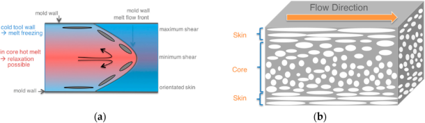
The flow lines are linear grooving, circular ripples or streaks of off tones on surfaces of molded parts. They usually appear in smaller areas of a component where there are restrictions to the flow of the material or change of cooling caused by non uniform wall thicknesses . The flaws usually take the form of bands or patterns along directions of material flow, and are especially apparent on complex geometries parts, or those with varying thickness of walls.
Root Causes of Flow Line Formation
Flow marks in injection molding have numerous causes, however as a rule, are caused by the fact that the plastic material is cooling due to uneven cooling at an uneven rate. This mismatched cooling, such as due to low injection pressure, leads to the typical patterning designs that are part and parcel of the flow lines, yet there are several causes of this inherent issue.
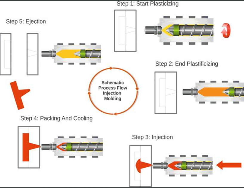
The main process that leads to development of flow lines includes changes in the velocity of flow of materials and cooling rates in a mold cavity as molten plastic passes through them. Different parts of the molten material flowing solidify differently because they cool at different rates resulting in variation of their surface textures and optical properties and this produces the patterns of visible flows that are the hallmark of this defect.
Material-Related Factors
The properties of materials have significant influence on the line of flows. The Melt Flow Index (MFI) of thermoplastics denotes the flow of the melted plastic; plastics of low MFI are more susceptible to flow marks whereas the higher MFI react better. Denser the viscosity of the materials, the higher the chances of the creation of the flow lines, whereas uniform cooling can help mitigate this issue .

The control of the temperature during the injection has an intense influence on the characteristics of the material flow. Inadequate barrel and nozzle temperature, affecting both the machine, will not allow materials to melt properly whereas a very high temperature may lead to deformation of materials. These two lead to uneven patterns in flows and resultant flow lines formation. Moreover, variations in the rates of material flow and injected speed are inconsistent, thereby resulting in cooling patterns, which are reflected in defects seen on the surface.
Machine Parameter Influences
Injection molding machines are tricky control points of the prevention of the flow lines. When the injection pressure of the machine is insufficient, the material will not be melted uniformly around the mold and will be uneven cooled. The improper injection pressure does not fill the cavity, and it provides conditions under which various injection molding defects including flow lines may develop.
Temperatures of barrels and nozzles should also be finely adjusted to ensure best property flow behavior. Cold temperatures cause lack of heating the material sufficiently and parameters of time like the residence time and the cycle length influences material temperature steadiness. Adequate heating of material can be inhibited by short cycling times whereas too long residence times can lead to material degradation, ultimately affecting the surface quality .
Mold Design Considerations
The design of molds, including gate location, has substantial influence on the occurrence of flow lines in several ways. Bad results will be realized on molds that have ineffective venting, variable wall thickness, and ineffective lubricant, whereas uniform wall thickness can lead to better outcomes. Such design weaknesses, often seen in poorly designed molds, pilot a smooth flow of material and cooling patterns that are uneven.
Shape of gate, runner and sprue have a direct impact on material flow characteristics within the mold cavity. Small gates and runners cause limiting stream of materials, which lowers pressure and temperature, enhances the formation of flow lines. Thickness differences in the walls introduce different rates of cooling that help to make the flow patterns recognizable.
Temperature Control Strategies
Proper temperature controlΘ demands the use of a gripped method of controlling several heating zones across the scope of the injection molding technique. There is an expectation that the material temperature must make a slow increase as the plastic is forced along the barrel whereby a guide of rule of thumb is +6 C through each zone. This heat difference will also allow the material to be optimumly conditioned as it traverses the injection system.
Flow line prevention requires equal importance on control of mold temperature. The cold molds expedite cooling process in the material and enhance better visibility in flow lines whereas the warm molds facilitate even cooling and patterns. Temperature monitoring and control systems allow accurate control over thermal conditions around the entirety of the molding procedure.
Pressure Parameter Optimization
Optimizing injection pressure is the art of maintaining a balance between several parameters in order to get a perfect flow of the material without secondary defects. Increased back pressure will aid to force the fluid through the runners/mold and improve compaction. The improved back pressure can allow better mixing of the material as well as uniformity of temperature prior to injection, which also helps to maintain uniform wall thickness .
Retention of pressure variations minimize the distinction of movement lines on finished products by holding compaction of material in the cooling process. Nevertheless, excess pressure also leads to other defects like jetting, so parameter balancing needs to be done to perfectly find the results.
Injection Speed Control
The pressure of injection has direct relation with speed of injection, the more the pressure the faster the flow rate of the substance. Speed optimization avoids the cooling of the material during injection and bears a complete filling of the cavity. Nominal injection speeds during the filling process reduce changes in flow that add up and cause flow line.
The considerations in material selection concern the proper selection of flow characteristics between the grades to be used according to the application. Flow materials with a higher flow can also lower the rate of injection speed expected without losing enough cavity filling at a cost of tradeoffs to other performance attributes like strength and dimensional stability.
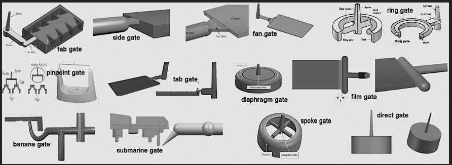
Gate and Runner System Design
The amplitude of proper size and positioning of gates has great influence on flow line occurrence. Small/thin gates and runners will limit and slow down flow of material causing a decrease in pressure, speed of injection and finally temperature, particularly in thicker areas . The right size gates allow the right flow of materials without exchanging pressure and temperature inappropriately during the injection process.
Design of the runner system should be able to meet material flow requirements and should limit the amount of pressure drop as well as temperature change. The positioning of gates, the runner size, and the nozzle diameter can be computer-simulated with optimal parameters to be found to maximize the bond-line potential with maximum cavity filling.
Venting System Requirements
Venting enables the trapped air in the mold cavity to leak after the molten plastic enters the mold. Adequate venting, along with the use of mold lubricant, will avoid air trapping which can change direction of the flow of the materials and induce the formation of flow lines. Opposite gates and vented ends as runner offer adequate air escape, during injection excessive injection pressure.
The specification over the depth of vents is also dependent on the material viscosity characteristics; the stiffer the material needs the deeper the vents. Weak venting forms back-pressure and breaks the flow of material, particularly affecting the plastic injection nozzle and heightens the point of flow line manufacturing process.
Mold Surface Considerations
Surface finishing of mold directly influences the visibility of flow lines on surfaces of finished products. Surfaces with greater polish will enhance flow patterns and surfaces with increased texture are capable of concealing small irregularities in flow, which helps to minimize flow marks . Surface treatments however are not essential alternatives to solve flow line problems since it does not cure ailments but merely symptomatic.
Pockets with sharp edges and corners in the molds will cause interferences to the flow thus making up of flow lines molten plastic cools. Mold design that has a fillet edge and rounded corners will enhance the flow of materials especially to the thicker regions as well as eliminate flow marks. Uniform material flow and the low possibility of visible flow patterns are promoted by smooth transitions flow freely.
Advanced Prevention Techniques
The computer simulation tools are useful in preventing the flow lines since it implies predicting the flow of the materials and the possible problematic areas before the mold is made. These tools allow possible optimization of gate placement, sizing of runners, and nozzle tip design in the cooling system to help prevent flow lines.
Process monitoring systems are able to identify the changes in parameters leading to the development of flows lines within the processing environment in real time so as to enable corrective action to be taken to ensure the optimal processing conditions prevail. The statistical process control methods assist in detecting trends, avoiding line flow occurrences by proactive control of parameters through parameter management.
Material Selection Guidelines
Flow line susceptibility is greatly determined by the material used so that not all polymer grades behave the same when it comes to the flow and the cooling properties. Materials of higher melt flow index have low flow line tendency in general, particularly when considering stored heat; however, the material selection requires a balance of the flow properties with other performance needs.
Additive packages have the capability to affect material flaw properties and the cooling behavior, possibly limiting the flow line in occurrence. But there are implications to other aspects of material performance and cooling phases lso, so trade-off between flow line and performance requirements must be evaluated closely.
Process Optimization Methods
Systematic process improvement entails a systematic assessment of machine settings, mould settings and material characteristics so as to reduce flow line formation. Design of experiments methods has the capability to determine the best combination of parameters by doing few trial and error iterations.
Periodic auditing of the processes will allow them to be maintained at the optimum level and eliminate parameter drifts that may translate to occurrence of a flow line. successful combinations of parameters can be documented; this will allow the same results in terms of quality exhibited to be produced consistently throughout production runs.
Quality Control Measures
Flow line assessment should also be clearly defined as part of visual inspection guidelines to guarantee standard quality of production. Measurement methods can measure the severity of flow lines and monitoring the improvement approach over time.
Use of statistical quality control techniques can be used in monitoring the variations in the process that lead to occurrence of the flow lines so that corrective measures can be taken before hand. Constant observation of the important process parameters will also help to keep conditions in which minimisation of flow line formation occurs.
Troubleshooting Common Issues
There are definite methods that can be used in systematic and trouble shoot in the particular causes of the problems of the flow line in specific applications. The techniques involved in process elimination can identify contributing elements and offer corrective procedures. Successful solutions can be documented and this will help solve the same problem quickly in future.
Proper maintenance of it eliminates parameter changes that induce the formation of flow lines when regularly cleaning the injection molding machinery. Temperature and pressure control systems were calibrated in order to control parameters during the run of the production.
Economic Impact and Cost Considerations
Defects on flow lines may have a considerable influence on the economics of production by causing the level of scrap, rework, and customer complaint. The prevention strategies, which aim to prevent flow marks, generally deliver positive returns on the quality costs and customer satisfaction.
Process optimization systems and process monitoring systems can and should provide significant long-run cost savings, by minimizing defect rates and stabilizing processes. The prevention resources are increased by the use of training programs of the operators and technicians to address issues like improper flow rate , which minimise the occurrence of flow lines.
Industry Applications and Standards
Different industries may have a different degree of acceptance of flow line defects, the automotive and consumer electronics applications often having the most stringent quality demands. There are medical devices which require special regulatory controls in terms of quality of surface and defect reporting.
Acceptable flow line as well as prevention strategies are given industry-specific guidelines and standards. It may be necessary to submit documented quality control procedures, and process validation procedures to comply with these standards.
Conclusion
One of the most complicated quality issues in a field of injection molding is flow lines, which involves high knowledge and awareness of the material, process, and principle of mold design. Effective prevention measures combine a number of methods such as temperature, pressure, optimal mold design, and a conventional way of managing the process. The most effective way of achieving flow line elimination is to find root causes and deal with them instead of applying superficial measures such as surface treatments or any other kinds of cosmetic solutions.