Cutting speed and feed rate define two primary parameters defining machining processes most of the temperature and tool life over time. These two criteria greatly affect the most desired surface finish, smoothness, precision, and efficiency of machined items. Ensuring best tool performance and increasing output depend on knowledge of how to compute and apply them.
What is Cutting Speed?

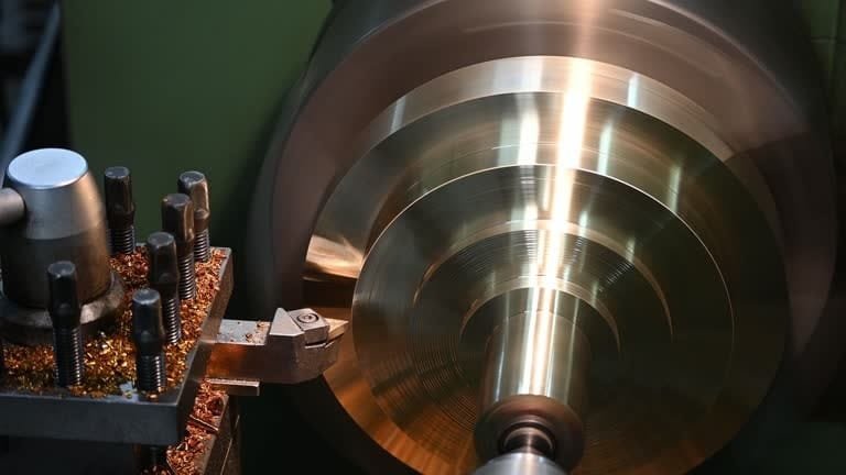
A cutting tool’s cutting speed can be defined as the relative speed at which the edge of the tool moves in relation to the material that is being machined. It is usually measured in m/min or SFM. Cutting tool advances’ speed is affected by machining technique, type of material, quantity of material, and tool material.
Importance of Cutting Speed

For best cutting speed, the proper optimum cutting speed depends on:
- The goal is to maximize the life of the tool. Cutting speeds that are too low may result in ineffective cutting, while cutting rates that are too high may cause the tool to overheat and wear out.
- Correcting cutting speed helps to improve surface smoothness and lowers vibration.
- A precise cutting speed increases rates of material removal, thereby boosting productivity.
How to Calculate Cutting Speed

The formula for calculating cutting speed is as follows: V = (π x D x N) / 1000
Located:
- V = m/min cutting speed
- D = Workpiece’s or cutting tool’s (mm) diameter
- RPM stands for revolutions per minute.
- π equals 3.1416.
Factors Influencing Cutting Speed
Ingredients Affecting Cutting Speed:
- Usually requiring slower cutting speeds, harder materials aid to reduce excessively high heat output and tool wear. In order to machine aluminum, for example, the cutting speed must be significantly faster than when cutting hardened steel.
- When compared to high-speed steel (HSS) tools, carbide tools are able to maintain higher cutting speeds due to their resilience to heat and their endurance.
- Utilizing the appropriate coolant helps to maintain temperatures at a consistent level, which in turn enables quicker cutting speeds without the risk of overheating.
- Machines that are sturdy are able to allow for higher speeds without experiencing excessive vibration or a loss of accuracy.
- The speed settings for tools with sharper edges and proper rake angles are different from those for instruments with dull or covered edges.
Practical Examples of Cutting Speed

- Steel (Mild): the recommended cutting speed ranges from 30 to 50 meters per minute.
- Cutting speeds of between 150 and 300 meters per minute are typically within the capabilities of aluminum.
- Titanium requires slower cutting speeds—typically 20 to 30 m/min—due to its heat retention properties.
What is Feed Rate?

Feed rate is the distance the tool advances across the workpiece surface in one revolution of the spindle. It is expressed either inches per revolution (IPR) or millimeters per revolution (mm/rev).
Importance of Feed Rate
Controlling the feed rate has an effect on the following:
- overly high feed rates raise tool breakage risk and wear.
- A slower feed rate can aid to improve surface quality; a greater feed rate could give a coarser finish.
- Perfect feed rates guarantee efficient material cutting without compromising quality.
How to Calculate Feed Rate
The equation of ideal feed rate is:
F = f x N x T
Where:
- F = Feed rate (mm/min)
- f = Tooth feed (mm/tooth).
- N =RPM’s spindle speed
- T = Cutting edge count—that is, teeth
Factors Affecting Feed Rate
Several elements influence the feed rate in some extent:
- Category of Tool: Multi-flute cutters provide for faster feed rates compared to single-point tools.
- Whereas softer materials may allow quicker feed rates, tougher materials demand slower settings.
- Surface Finish Requirements: Sometimes fine finishes demand for reduced feed rates to generate more even results.
- The stability of the workpiece depends on its material. Rigid workpieces can handle higher feed rates, whereas flexible sections may require slower settings to reduce vibration.
- Feed rates should be dropped gradually as the tool dulls maximum tool life while maintaining production.
Practical Examples of Feed Rate
- Aluminium Milling: The feed rate for aluminium milling could range anywhere from 0.1 mm/tooth to 0.3 mm/tooth on average.
- Feed rates of 0.05 to 0.15 mm/rev are required for turning mild steel.
- Titanium Drilling: Feed rates for titanium drilling are usually slower, ranging from 0.02 to 0.08 mm/rev, due to the material’s toughness.
Best Practices for Setting Cutting Speed and Feed Rate

Utilizing the best practices that are listed below will assist you in achieving optimal cutting speed and the highest possible performance in machining:
- It is important to adhere to the recommendations provided by the manufacturer. Product makers typically provide guidance on the appropriate cutting speeds and feed rates for specific equipment and materials.
- Experiment with Different parameters: Use sample materials to experiment with different parameters until you discover the sweet spot for output and accuracy.
- Examining tool edges lets one ascertain whether adjustments are needed to increase tool lifetime.
- Respond to Variables: Adjust feed rates and tool speeds as needed to accommodate different materials, machine capacities, and other factors.
Adjusting Speed and Feed for Different Materials
- Aluminum can keep better speeds and modest feed rates because to its softer build-up.
- Even though cutting speeds should be moderate, aggressive feed rates are required while working with cast iron.
Techniques for Balancing Speed and Feed
When you combine optimal feed rate with speed, you need to carefully consider these factors:
- Constant chip thickness ensures efficient material removal or tool overloading prevention.
- Depth of Cut: To maintain accuracy, a depth of cut increase could require reducing feed rates.
- The optimal tool routes allow one to increase efficiency while decreasing vibration and wear.
Common Mistakes to Avoid
Errors in feed rate and cutting speed setup can lead to bad outcomes. Essential mistakes include:
- When you go at too high a speed, you risk overheating, damaging your tools, and getting a smooth surface.
- Operating too slowly drives ineffective material removal and increases machining time.
- Misaligned Results Occur When You Don’t Pay Attention to Tool Wear.
- Inappropriate lubrication can cause friction and tool life reduction in coolant use.
- Every material has unique characteristics that demand particular speed and feed settings; so, one should overlook material properties.
Applications in Different Machining Processes
- When turning a workpiece, it is essential that the tool feed and spindle speed be in perfect harmony with one another.
- Milling with multi-flute tools demands for exact feed per tooth computation.
- When cutting, the speed has a direct correlation to the drill’s penetration rate and the amount of heat it produces.
- While grinding, it is important to keep the cutting speeds low to avoid overheating and ensure clean finishes.
CNC Machining Considerations
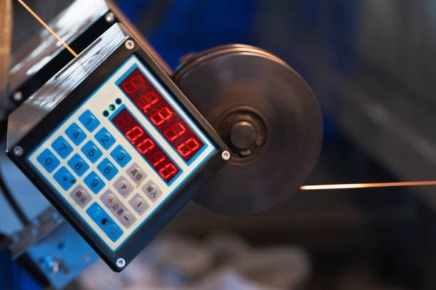
To achieve the desired results in CNC machining processes, the feed rates and cutting speeds are precisely regulated. Modern CNC systems enable real-time input that helps to improve machining precision by which ideal cutting speed is changed.
Conclusion
The ability to accurately and efficiently manipulate feed rate and cutting speed is crucial for producing high-quality machined parts. By exactly computing these factors in view of material properties, tool attributes cutting temperature, and milling machine restrictions, manufacturers may maximize tool life and boost production. Testing and observation will help to fine-tune these values such that, in many machining processes, the outcomes improve.
FAQs About Feed Rate and Cutting Speed in CNC Machining
Decoding CNC Terminology: Cutting Speed, Feed Rate, Spindle Speed, and Feed Per Tooth
A grasp of the basic of CNC machining procedures and variables would help one to achieve best cutting outcomes. The rate of feed, feed per tooth, cutting speed, and spindle speed are the four primary variables that mostly determine the amount of material removed by your CNC machine. Every helps in different ways to define the degree of success and quality of your machining and cutting process. Let’s now dissect them:
- The rotational velocity of a spindle is denoted by its revolutions per minute (RPM). Even while they may improve cutting efficiency, improperly regulated higher spindle speeds generate excessive heat and tool wear.
- The cutting speed, expressed in SFM or m/min, is the rate at which the cutting tool’s tip travels across a material’s surface. This determines essentially the tool life. Running the cutter at excessively high speeds can rapidly damage tools.
- Feed Rate (in millimeters per minute or inches per minute): This measures the rate at which the cutting tool is advanced into the material. The feed rate determines both the job’s efficiency and the surface finish of the workpiece in great importance.
- Machine feed rate, expressed as feed per tooth (IPT) or millimeters per ton (mm/t), is the rate at which milling cutters remove material during a single revolution. Knowing feed per tooth will help one to precisely determine the suitable feed rate for efficient cutting.
Why Do These Parameters Matter?
Correcting best machining results rely on appropriate variable setting. Tools can be damaged, surfaces can be poorly finished, tool wear can be excessive, and machining time might be increased due to inaccurate settings. Always refer to the indicated speed and feed settings advised for the material type and tools you are using to guarantee optimal efficiency and quality.
Understanding SFM and Its Relation to RPM and Cutting Speed
SFM (Surface Feet per Minute) is the key word used to indicate the actual cutting tool speed across material surface. It is not identical to RPM (Revolutions Per Minute), but they do have some commonalities. RPM is the spindle’s rotational speed; SFM measures surface speed, the linear speed of the cutter as it interacts with intended surface of the material.
How to Convert RPM to SFM and Vice Versa
These equations assist to ensure accurate computations:
- Feet per minute, or SFM, here is equal (RPM x π x Diameter) / 12 (inches).
- m/min = π x Diameter / 1000 (mm) RPM
In terms of SFM or m/min, a bigger, softer cutting tool materials will achieve a higher cutting speed when both tools are spun at the same RPM. This occurs since the outermost edges of the larger cutting tool material have to travel a longer distance every turn.
Understanding the Difference Between Cutting Speed and Cutting Velocity
Cutting velocity and cutting speed are two distinct concepts in computer numerical control (CNC) machining, despite their frequent interchangeability machine tool capability.
- Cutting speed (N) stated in RPM is the rotational speed of the spindle.
- The cutting velocity, express as a tangential speed with respect to the material, is measured in standard foot-minutes (SFM) or meters per minute (m/min). Formula for cutting speed:
The value of Vc can be expressed as πDN divided by 1000, where D is the diameter in a mm unit.
When the tool diameter is increased while the RPM remains constant, the cutting speed increases. Example: a cutting tool engages the Vc for a 25 mm tool operating at 1000 RPM is approximately 78.5 m/min. The cutting force and Vc for a tool with a 50 mm diameter and the same RPM are nearly 157 m/min chip load. Direct consequences of this variation are on rates of material removal, heat generation, and tool life excessive tool wear.
The Importance of Matching Feed Rate with Cutting Velocity
Getting desired outcomes calls for precise control of cutting speed and feed rate. Usually a greater cutting speed requires a higher feed rate to maintain constant chip thickness workpiece material. Ignoring this relationship could result in poor-quality finishes threading tools, inadequate back material removal rate, and too high tool wear. Both the efficiency and quality of your machining processes will increase once you learn to balance.