Introduction
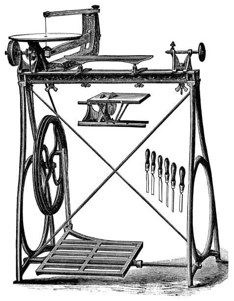
One of the most flexible and useful machine tools available in manufacturing, a lathe lets materials including plastic, metal, and wood be precisely shaped. The right cutting tool is fundamental in lathe operations since it shapes and finishes the workpiece. Machining operations’ success mostly relies on the type of cutting tool used, its material, geometry, and cutting parameters.
Including their varieties, materials, geometry, tool holders, and best practices for obtaining exceptional machining results, this thorough guide investigates all you need to know about lathe cutting tools.
Types of Cutting Tools in Lathe

Applications, number of cutting edges, and intended use all help to define the types of lathe cutting tools. Knowing these kinds helps machinists choose the correct tool for particular machining jobs.
1. Single-Point Cutting Tools
One cutting edge of single-point cutting tools interacts with the workpiece to remove material. Mostly used in turning operations on a lathe, these tools Common single-point cutting tools consist in:
- Designed to cut a workpiece’s diameter and produce cylindrical forms, turning tools
- Facing tools cuts across the workpiece’s face to produce a smooth surface.
- Pre-drilled holes are enlarged to exact diameters using a boring tool.
- On a workpiece, thread cutting tools create either internal or external threads.
- Grooving tools produce on the workpiece small channels or grooves.
2. Multi-Point Cutting Tools
Multiple different cutting tools and edges of multi-point cutting tools interact concurrently with the workpiece. Operations needing high material removal rates find use for these instruments. Here are some examples:
- Made for hole drilling in a workpiece are drill bits.
- Used for a variety of milling operations but occasionally modified for lathe work are milling cutters.
- Reamers are used for exact dimension sizing and finishing drilled holes.
Cutting Tool Materials

The performance, cutting speed, and durability of a cutting tool depend much on its material. Lathe cutting tools mostly consist in the following materials:
1. High-Speed Steel (HSS)
Because of its hardness, wear resistance, and heat resistance, HSS is a common material for many cutting tools for lathes. It is perfect for general-purpose lathe operations since it stays cutting edge at high temperatures.
2. Carbide Tools
More wear-resistant and harder than HSS tools are carbide tools. Perfect for machining hard materials like stainless steel and cast iron, they can cut faster. Two basic forms of carbide tools are
- Made totally of carbide material, solid carbide tools
- Replaceable tips made of carbide inserted on tool holders offer reasonably priced performance.
3. Ceramic Cutting Tools
Applied for high-speed machining of hard materials, ceramic tools have outstanding heat resistance. They are brittle, though, and need careful handling to avoid breakage.
4. Diamond and Cubic Boron Nitride (CBN)
Extremely hard materials are cut and ultra-precision machining is accomplished using these tools While CBN tools are best for machining hardened steel, diamond tools provide outstanding surface finishes.
Cutting Tool Geometry
Cutting efficiency, chip removal, and tool life of a cutting tool depend on their geometry. Important elements of cutting tool geometry consist in:
- Rake Angle Affects cutting forces and chip formation. A negative rake angle strengthens tools; a positive rake angle reduces cutting force.
- By preventing the tool from rubbing against the workpiece, clearance angle helps to lower friction and heat generation.
- Cutting edge angle defines the distribution of cutting forces.
- Affects tool lifetime and surface finish: nose radius. Larger radii increase finish but demand more cutting power.
Tool Holding and Mounting

In lathe machining, accurate, stable tool holding guarantees precision and stability. Tool posts and tool holders secure cutting tools so as to prevent vibrations and misalignment.
Tool Holding Components
- Tool Post: Easily adjustable and holds the cutting tool.
- Tool Holder – Offers the cutting tool safe clamping and alignment.
- Replaceable cutting edges called carbide inserts increase machining efficiency and help to extend tool life.
Factors Affecting Cutting Performance

The efficiency and quality of lathe machining processes depend on several elements, including:
- Cutting speed is the workpiece’s rotating speed. Faster speeds cut machining time but can wear tools more quickly.
- Feed Rate: Affecting surface finish and material removal rate, the speed of tool movement into the workpiece determines
- Depth of Cut: The pass-through material removal total. While they demand more cutting forces, deeper cuts improve machining efficiency.
- Reduces heat and friction by coolant or lubrication, so extending tool life and enhancing surface finish.
Best Practices for Using Cutting Tools in Lathe

Using these best practices will help you to get ideal results in lathe machining:
- Choose the suitable cutting tool depending on the machining conditions and material.
- Maintaining sharp cutting edges: Frequent sharpening or replacement of cutting tools helps to avoid inadequate surface finish.
- Use correct tool geometry; change rake and clearance angles to maximize cutting performance.
- Guarantee Stable Tool Holding: Correct tool holding will help to reduce vibrations and errors.
- For effective machining, control depth of cut, feed rate, and cutting speed.
- Apply lubrication or coolant to help to lower heat generation and extend tool life.
- Regular tool inspections help to maintain high machining efficiency by allowing one to find wear and replace tools when needed.
How to Select the Right Lathe Cutting Tool?

Gaining precise and high-quality results in machining business demands the correct selection of lathe cutting tools. Choosing the right lathe tools tool is crucial for efficiency, accuracy, and longevity of both the power source tool and the The component. Several key factors determine known as ideal lathe cutting tool, including coating type, workpiece material, milling operation, and required part shape.
1. Lathe Tools Coating
Coatings are applied to the outer surface of a cutting tool to improve its durability, wear resistance, and heat dissipation. Usually lasting more than uncoated tools, coated carbide lathe cutting tools are a preferred choice for industrial uses. Most often used coatings on lathe cutting tools are the following:
- The titanium Nitride (TiN): Provides increased hardness and wear resistance while reducing friction during cutting operations.
- Titanium Carbide (TiC): Offers superior toughness and wear resistance, making it suitable for cutting hard metals.
- Aluminum Oxide (Al₂O₃) increases thermal resistance, so enabling the tool to survive high temperatures without losing sharpness.
2. Workpiece Material
The mechanical properties of the the work piece play a significant role in determining the most suitable a lathe cutting tool. Hard materials require specialized tools, that are strong enough to withstand machining forces without breaking or chipping. Below are a number examples of how tool material selection is influenced by workpiece hardness:
- Soft materials—such as aluminum, brass, mild steel—high-speed steel (HSS) or uncoated carbide tools will suffice.
- Hard materials—such as cast iron, hardened steel, or stainless steel—Diamond or Cubic Boron Nitride (CBN) tools are perfect because of their great hardness.
- Brittle materials (e.g., ceramics, composites): Carbide or diamond tools work best as they offer precision cutting without excessive wear.
3. Desired Turning Operation Type
Each machining operation requires a specific cutting tool designed for the task. Selecting the appropriate tool for the operation improves accuracy and effectiveness. Examples of different types of tools and how tool choice fits machining operations are below:
- Turning operations: Requires a rough or finish turning application to decrease workpiece diameter.
- Facing operations: Uses a directed tool to create a smooth, flat the floor on the workpiece.
- Thread cutting: Requires a thread limiting tool to generate spiral thread designs on cylindrical parts.
- Boring operations: Uses a boring tool to increase existing holes for precision finishing.
- Cutting small channels on the workpiece calls for a grooving tool.
4. Required Part Shape
The geometry and form of the final part affect also the choice of a lathe cutting tool. The tool must match the intended workpiece profile to ensure accuracy. Examples include:
- Cylinder-like workpieces: Roughing or finishing converting equipment.
- Flat surfaces: Facing tools.
- Internal holes: dull tools.
- Complex geometries: Forming tools.
- Knurled surfaces: Knurling tools with rolling patterns.
Components of a Lathe Cutting Tool
All lathe cutting tools have similar components that define their cutting efficiency and utility despite differences in design. Below are the key parts of a lathe cutting tool:
1. Shank
The shank has the main body of the cutting tool that joins to the lathe machine. It guarantees structural stability and helps the tool to stay firmly in place during machining. For optimum rigidity, shanks usually have a rectangular or square cross-section.
2. Face
The area the chip flows across during machining forms the face of the cutting tool. The geometry of the face impacts the tool’s performance by influencing chip direction and heat dissipation.
3. Flank
The flank is the surface of the tool that interacts with the workpiece. It can be categorized into:
- Major flank: The primary show up that faces the workpiece and contributes to the limiting action.
- Minor flank: The secondary appear that supports the tool’s stability at machining.
4. Cutting Edge
The cutting edge is the active part of the tool responsible for removing material from the the component. based on the tool type, it can have separate orientations and angles to perform the cutting process and surface finish.
5. Tool Nose
The tool nose is the intersection across the main along with minor cutting and sharp edges off. It often appears a curved radius, which strengthens:
- Tool strength
- Smoothness of the cut
- Longevity of the tool
6. Side Rake Angle
The side by side rake angle is formed by the tool face, rotating workpiece and a line adjacent to the body. This angle influences an chip flow direction and sets how easily the chips move away from the workpiece.
7. Side Relief Angle
The side relief angle is the position between the major flank and the shank surface when viewed via the front. It assures that the major flank does not rub against the workpiece, preventing excessive wear.
8. End Relief Angle
When viewed from the side, the end relief angle is the perspective between the resulting in edge of the flank along with a line normal to the tool’s base. This angle keeps the minor the flank from making contact with the workpiece and ensures smooth cutting action.
9. Back Rake Angle
The angle formed by the tool face against a plane parallel to the tool base is the back rake angle. It determines the sharpness of the cutting edge:
- A high back rake angle enhances sharpness but reduces tool strength.
- A low back rake angle improves tool durability but may require more cutting force.
10. End Cutting Edge Angle
Formed between the end cutting edge and a line perpendicular to the tool body, the end cutting edge angle is This angle guarantees that the cutting edge does not scrape against the finished surface of the workpiece, so lowering friction and increasing accuracy.
11. Side Cutting Edge Angle
The angle formed by the side cutting edge between a line parallel to the body of the tool is known as its side cutting edge angle. It plays a crucial role in:
- Chip thickness control
- Cutting force distribution
- Overall machining efficiency
Four Categories of Lathe Cutting Tools
Lathe cutting tools are classified into four main categories based on material, tool operations, structure, and feed direction. Knowing these categories helps machinists choose the right tools for particular jobs, so improving accuracy and production.
Category 1: Lathe Cutting Tools Based on Material
Category 1: Lathe Cutting Tools Based on Material The choice of material for a lathe cutting tool significantly influences its durability, cutting speed, and effectiveness. The most often used materials in manufacturing lathe cutting tools are below:
1. High-Speed Steel (HSS)
High-Speed Steel (HSS) contains parts such as tungsten, carbon, vanadium, and chromium, which contribute to its hardness, strength, and wear resistance. These tools retain the cutting edge at high temperatures, making them suitable for rough and semi-finish turning operations. HSS tools are widely used due to their affordability and versatility.
2. Carbide Tools
Carbide tools are composed of tungsten carbide particles bonded with cobalt, making them extremely hard and wear-resistant. They are capable of cutting through tough materials at higher speeds compared to HSS. Carbide tools are more costly and brittle, which limits their use in some machining operations, though.
3. Diamond Tools
Diamond cutting tools are the hardest known tools, making them ideal for precision machining. Excellent for cutting non-ferrous metals, ceramics, and composites, their great cost limits their general industrial application.
4. Cubic Boron Nitride (CBN) Tools
Second in hardness to diamond, cubic boron nitride (CBN) tools are also quite durable and abrasion-resistant. In rough and sporadic cutting applications, they particularly help machining cast iron and hardened steel.
Category 2: Lathe Cutting Tools Based on Operations
Furthermore classification of lathe cutting tools depends on their machining operations. Every kind different lathe cutting tools is meant for a particular use during manufacturing.
1. Turning Tools
Turning tools shrink the workpiece’s diameter by removing material along its length. Two subtypes exist from them:
- Used rapidly to remove a lot of material, rough turning tools help to prepare the workpiece for finishing.
- Finish Turning Tools – Designed to remove small amounts of material to create a smooth, precise surface.
2. Chamfering Tools
Chamfering tools produce slanted workpiece edges. While turning tools can also perform chamfering, they must be set at the correct angle. More accuracy and efficiency come from dedicated chamfering tools.
3. Thread Cutting Tools
On cylindrical components, spiral threads are made with thread cutting tools. The nose angle of the tool is determined by the required thread angle, while the tool’s cross-section affects the thread pitch.
4. Facing Tools
Facing tools use their side-cutting edge to remove a thin layer of of material, producing a smooth, flat surface on the end of the workpiece.
5. Forming Tools
Forming tools combine turning and grooving operates, allowing for the creation of complex shapes in a single go by. They enhance accuracy and efficacy, reducing the machining cycle time.
6. Grooving Tools
Grooved tools create narrow channels or grooves on cylindrical workpieces. The lines can be V-shaped, square, or rounded, depending on the tool’s geometry.
7. Boring Tools
Boring tools consist of a boring bar or block with a cutting edge at the finality. They are used to broaden pre-drilled holes to achieve the desired diameter and accuracy.
8. Knurling Tools
Used to produce indented patterns on a workpiece, knurling tools feature two or more metal rolling wheels with embossed designs. These patterns enhance the grip and aesthetic appeal of the component.
Category 3: Lathe Cutting Tools Based on Structure
A turning machine cutting tools can also be categorized based on their structure composition and method of assembly. The three main types are:
1. Single-Body Tools
Made about a single piece of material with a predefined shape, single-body tools follow geometry. Their durability, security, and great cutting speed make these variables tools rather popular.
2. Welding Lathe Cutting Tools
Separately headed and accepted together through welding, the welding lathe cutting tools Usually from a hard material like carbide, the cutting edge is created; the rod is made from another metal. Though less cutting force than single-body tools, these tools are reasonably cheap.
3. Clamp Lathe Cutting Tools
Made of replaceable cutting inserts placed onto a handlebar using a clamping mechanism, clamp lathe cutting tools consisted. For many machining processes, those diamond lathe cutting tools are quite effective because they are flexible, easy to replace, and adjustable.
Category 4: Lathe Cutting Tools Based on Feed Direction
Lathe cutting tool direction of feeding into the workpiece defines its classification. Three main categories exist:
1. Right-Hand Lathe Cutting Tools
On machining, right-hand cutting tools travel from right to left. Someone designed like the human hand; the main cutting edge is on the left against one another of the cutting tool operations and the right thumb indicates the feed strategy.
2. Left-Hand Lathe Cutting Tools
Tools for left-hand limiting cut material from left to right. The left thumb indicates the feed direction according to the human hand analogy; the main cutting edge runs on the right side of the tool.
3. Round-Nose Lathe Cutting Tools
Round-nose tools have no defined side rake or back rake angles thus they can move in both left-to–right and from right to left directions. For smooth finalizing processes needing few surface flaws, they are appropriate.
Common Lathe Cutting Problems and Solutions
1. Excessive Tool Wear
Cause: wrong tool material or cutting speed.
Use premium tool materials and suitable cutting speeds
2. Poor Surface Finish
Dull cutting tool and improper nose radius cause.
For a better finish, sharpen tools and change tool geometry.
3. Vibration and Chatter
Cause: too strong cutting forces, loose tool holding.
Solution: Secure the tool properly and adjust cutting parameters.
4. Built-Up Edge (BUE)
Low cutting speeds and incorrect lubrication cause:
The answer is to apply enough lubrication and speed cutting.
Conclusion
Lathe cutting tools are essential for machining operations since they help to shape them, so influencing productivity and accuracy. Understanding many kinds different types of lathe cutting tools, their materials, geometry, and best practices helps machinists produce excellent results while extending tool life and maximizing machining efficiency. A machining operation’s accuracy, efficiency, and durability depend on choosing the correct lathe cutting tool. Factors including coating, workpiece material, operation type, and desired part shape will all affect the decision. Knowing the elements of a lathe cutting tool also enables machinists to maximize tool life and performance.
In industrial and CNC machining operations, manufacturers can increase output, lower costs, and guarantee excellent results by selecting the suitable cutting tool for every application.