Meta Description: Learn to control standard machining tolerances and rail cutting tolerances along with CNC machining tolerances with our in-depth guide on 2024. Get to know the kinds of tolerance, calculations, and standards, and optimization techniques to achieve precision manufacturing.
In life, winning is in precision and in today scenario of cut throat manufacturing industry precision is the key. CNC machining tolerances should be at the basis of quality control, either your parts do pass the rigorous standards or are sorted out for rejection. This knowledge of the critical parameters is what could make or break a manufacturing process and thus tolerance knowledge is a prerequisite in the circles of engineers, manufacturers and quality control personnel the world over.
Understanding CNC Machining Tolerances Fundamentals
CNC machining tolerances are a level of adjustability in the manufactured components regarding them being out of pointing stated in the dimensions. They determine how much variation is acceptable by ensuring the functioning of the part is maintained without putting too much strain on it and as well addressing the geometrical tolerances and manufacturing constraints. Tolerances in modern CNC machineries have been extraordinarily precise, with to the lid rank of tightness that is generally set between +/- 0.005″ and +/- 0.030″, depending on parts and requirements.
Tolerance can be said to be directly related to manufacturing accuracy, the smaller the tolerance, the more accurate the manufacturing but also the more expensive and the more complex. Any manufacturing process cannot produce dimensional accuracy, so tolerances play an important role in the definition of acceptable limits of quality. The CNC technology has made it possible to get tolerance like never before in many manufacturing possibilities across material and geometrical considerations.
Essential Terminology for Machining Tolerances
To interpret machining tolerances, it is important to be acquainted with important terms in tolerance classes and precision manufacturing which establish the basis in communicating in precision manufacturing. The nominal size is the theoretical size as used on engineering drawings, the size which manufacturing processes should attempt to make. All calculations in tolerance start with this nominal dimension as reference point.
Actual size is the dimension of the part measured after machining is done. Basic sizes are theoretical in nature whereas actual sizes are the results achieved in real life situations during manufacturing. The correlation between actual sizes and basic sizes defines the existence or lack of quality of parts. Proper manufacturing reduces the gap between these values based on material properties without reducing the functionality of parts.
Limits describe the largest and the smallest acceptable size of manufactured parts. The upper and lower limits define the maximum acceptable size and minimum acceptable size respectively. An element that does not fit into these specification limits is rejected, and this stresses the need to exercise dimensional control during the manufacturing process.
Deviation Calculations and Their Applications
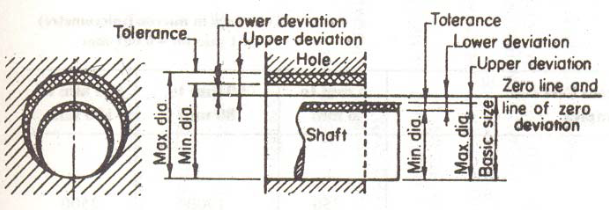
Deviations measure how consistency compares to the specified limits of actual part sizes, giving or rather serving as important feedback to optimize the process. Upper deviation will be the difference between the upper limit and the basic size and lower deviation will be the difference between the lower limit and the basic size. The calculations assist manufactures in knowing the process capability as well as areas of improvement.
Mathematical accuracy in the calculation of deviations makes sure that there is quality control on different runs in production. The symbols of positive and negative deviations imply that there is more than the basic size, and less than specification respectively. These associations are important in assisting manufacturers to make adjustments earlier on as opposed to making adjustments at the end of the day when faced with quality problems.
This is because deviations can be systematically followed and as such the implementation of statistical process control is possible since the manufacturer will be able to anticipate any trouble that could arise as far as quality is concerned. This is more of a proactive strategy that minimizes wastage, enhances efficiency and keeps the customer satisfied due to the constant quality of parts.
Datum Reference Systems in Precision Manufacturing
Datum systems form reference lines along dimensions in such a way that they form a uniformity in the measurement of the dimensions of various operators of equipment. These dashed lines or sheets provide the basis of the geometric dimensioning and tolerancing (GD&T) use. Effective selection of datum will guarantee repeatability and accuracy in measurement.
Good machining methods take into account part geometry, functional constraints and the manufacturing constraints. Primary datums are used to form the main reference system with secondary and tertiary datums giving extra positioning control. This two-tier system allows in-depth management of the control dimensions during the manufacturing process.

The choice of suitable datums has a severe influence on the accuracy of measurements and functionality of the part. Engineers should be thinking about the use of the parts in the end assembly, and the type of datum made should favor the assembly efficiency as well as serve to meet functional needs. The ineffective selection of datum may cause confusion of measurement and quality.
Material Condition Concepts: MMC and LMC
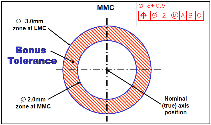
Maximum Material Condition is at the same level with parts having maximum amount of material subject to the specified tolerances. In external aspects, such as the pins, MMC is the upper acceptability dimension but in internal aspects such as the holes MMC is the lower acceptable dimension. Knowing MMC can enhance the best utilization of very tight tolerances.
Least Material Condition (LMC) is the reverse case and parts are made with minimum material within the tolerances. LMC is very important when it comes to components within the tolerance band of custom strength or weight restriction. The tolerance range that can be allowed in the manufacture is determined by transition between MMC and LMC.
Bonus tolerances are productions based on bond amongst MMC and actual part conditions. When some of the parts are lowered on the MMC to LMC, extra tolerance is introduced to be made use of on other characters of dimensions. This principle enables manufacturers to allocate tolerance in the most optimal way, without losing the functionality of a part and its assembly needs.
Comprehensive Tolerance Types and Classifications
Unilateral tolerances permit variation of dimension in a single direction only of the basic size. This type of tolerance ensures that one of its boundaries is strictly controlled and the other one becomes flexible. Examples of application include cases where particular dimensions of minimum or maximum are of vital importance in terms of performance or safety.
The unilateral tolerances have a clear direction in their mathematical representations of the tolerances. As an instance, a dimension a dimension that reads 10.0 + 0.5/- 0.0 mm can only be varied positively and one requires a minimum dimension of 10.0 mm. The method gives clear machining processes and manufacturing directions and still includes functional needs.
The case of unilateral tolerance application involves bearing fits, shaft dimensions cannot assume certain limits and the case of clearances where minimum gaps should be provided. Realization of the role of the unilateral tolerances and when to use them aids in maximizing part functionality and minimizing the requirements on the manufacturing activity.
Bilateral Tolerance Implementation Strategies
Bilateral constraints allow dimensional tolerance in both directions to thechosen size balancing the flexibility in the manufacturing process. This method of tolerance is the commonest to be used in all general machining where one would just use equal variation on either sides ensuring that the part works within a narrow range . Symmetrical design makes planning of production and quality easier.
Bilateral tolerances are written with equal reverse and forward limits that are written as Example: +0.X mm (mm) Unbalanced bilateral tolerances result in a differing positive and negative tolerance offering toleration to asymmetrical functional needs. Such flexibility enables the engineer to allocate tolerances in an optimum manner depending on those requirements of a particular application.
The choice of equal or unequal bilateral tolerances is based in the part functions, the manufacturing of them as well as in assembly need. Equal tolerances make manufacturing, and inspection simpler, unequal tolerances make solid control of critical dimensions. The two may be applied in the precision manufacturing.
Limit Tolerance Advantages and Applications
Limit tolerances No reference to any basic sizes is given, and tolerance limits set direct limits to the manufacture, upper and lower. It does away with calculation whilst conveying reasonable height and width specifications in a clear manner. Limit tolerances are especially useful when used at the production floor.
Among the real-life benefits of limit tolerances are: that inspection becomes easier as well as measurement confusion decreases, thus potentially lowering manufacturing costs . Inspectors do not compute practical measures by finding permissible ranges according to basic measures and tolerances but compare them directly with measures set. Such a smooth process lowers the chances of mistakes and enhances performance.
Limit tolerances benefit manufacturing processes in that there is increased communication and less complexity of the set up. Machine operators are able to give attention to keeping dimensions within the designated ranges instead of computing the acceptable deviation of the nominal values. This method is especially useful in those high-volume production situations in which simplicity and speed are imperative.
Geometric Tolerance Fundamentals
Profile tolerances also regulate form and shape of features of part construction, not just dimensional control, but also covering contours of a surface profile, features of cross-sections, etc. Profile tolerances differ with dimensional tolerances in the concentration on a specific measurement, whereas profile tolerances guarantee theoretical feature compatibility to design purpose. this generalized method is critical with complex shapes.
Tolerances on the profile dimensions would need advanced inspection gear that would incorporate assessments of surface curves relating to hypothetical profiles. These measurements are usually done with Coordinate measuring machines (CMMs) and optical scanners and compare reference surfaces with CAD model representations. Functional requirements of profile tolerance verification meets the entire feature requirement.
Examples of profile tolerances applications are aerodynamic surfaces, sealing interface, aesthetic applications and other areas in which overall shape accuracy is important to performance. Profile tolerance control is great in critical applications that have tight tolerances on shape control due to its comprehensive design.
Orientation Tolerance Control Methods
The angular relations between features of parts and reference datums are governed by orientation tolerances which otherwise will not fit properly to each other and fail to assemble properly and operate. These tolerances also govern perpendicularity, parallelism and angularity with no explicit examination of the dimensional size. Mating parts and mechanical assemblies all need an orientation control.
Tolerances as applied to perpendicularity serve to precision of surfaces relating to their 90 degree orientations with regard to datums in reference, which is important towards bearing fits and internals assembly. Parallelism tolerances take care of the surfaces which are parallel to each other and make them well spaced and aligned. Angularity tolerances define absolute relationships of the angularity of angled features and beveled sides.
Orientation tolerances need proper datum set up and inspection strategies in order to measure them. General tools that assure the accuracy include digital indicators, precision squares, and CMMs in orienting it. Correct orientation control leads to assembly of parts in the right manner and ensuring that the parts can work as they should.
Location Tolerance Applications
Location tolerances lay down the positional tolerance acceptable of feature to datum references so that the features are aligned appropriately and aid in assembly match-up. These tolerances regulate the positions of the features and not the size or shape of the features. Positional tolerances are especially significant to hole patterns and mounting interfaces.
True position is the ideal location of features and the concept of position tolerances refers to the permissible deviation of the same. The circular or cylindrical zone of tolerances produced by the position tolerances allow an engineering tolerance with regard to manufacturing variation of assembly requirements. It is a practice aimed at maximizing tolerance distribution on targeted needs.
Location tolerances Location tolerances are used in instances where the location of bolthole patterns is important to align fasteners correctly, and bearing bores where position location influences assembly and performance. Knowledge of location tolerance would help engineers to determine correct controls of critical features.
Form Tolerance Standards and Measurements
The physical properties of individual features, such as straightness, flatness, circularity and cylindricity, are governed by form tolerances. Such tolerances achieve a feature that is satisfactorily shaped regardless of size and location. Form control is important in sealing surfaces and bearing journals and in precision interfaces.
Tolerances on straightness regulate the extent that linear features are not straight just like straight rails and machine ways are. Flatness tolerances are tolerances that guarantee surfaces have planarity within an acceptable range, which is significant in case of gasket surfaces and reference planes. The geometric characteristics of rotating parts, i.e., their roundness and shape are regulated by circularity and cylindricity tolerances.
Tolerances on form measurement necessitate precise instruments that have the capability to measure changes that are very small in magnitude and variations. accuracy in form verification is achieved by use of surface plates, precision straightedges, roundness testers. Correct form control produces an optimum part performance and life.
Runout Tolerance Control Techniques
Surfaces when rotated are controlled by runout tolerances that incorporate both form, orientation and location control into a single specification. This an holistic process is most helpful on components that require rotational interactions to match several geometrical properties at the same time. The runout check conditions simulate genuine running conditions.
Where circular runout governs maximum range of variation within a given number of cross-sections in rotation, total runout governs variation over the whole surface. The choice between the total runout and circular is based on the functional requirement and the manufacturing capacity. The two methods offer useful control of rotating parts.
The measurement of runout needs exclusive equipment that is in a position to rotate parts, checking the change in surface. Dial indicators and electronic probes follow surface deviation in the rotation and offer direct data of component quality. Control of runout provides free operation and a long life of components.
Standard CNC Machining Tolerance Ranges
The contemporary CNC machining operations commanded a high degree of tolerance in varied use. Typical high tolerance machining CNC milling processes are controlled to 0.005 inch (0.13 mm) (to either side) and higher specification capabilities can be achieved on specialized applications. It is owing to these abilities that CNC machining is applicable in the critical precision tasks.
Various CNC process have different tolerance depending on tooling, materials and operating parameters. CNC turning machine tools work exceptionally well to hold tight tolerance on cylindrical constituents and multi axis milling machines allow control of complex geometry. Learning about process capability assists engineers to choose the suitable production procedures.
Standard tolerances can only be achieved through the following; maintenance of machine condition, control of environment, and discipline in operation. Tolerance capability can be compromised by temperature changes, wear of tools and set up when manufacturing plastic parts . By running consistent conditions, one could ensure consistent tolerance accomplishment between successive production lots.
Cost-Benefit Analysis of Tight Tolerances
Tighter tolerances have a direct effect on the costs of manufacturing by adding machining time, special tooling and greater inspection needs. There is an exponential correlation of tolerance tightness and cost that involves thoughtful consideration of functional necessity with respect to manufacturing economics. Optimization reconciles the requirement of performance and cost.
Specification of tight tolerances must be evaluated based on part functionality, assembly and production capability. This aspect works since critical characteristics that need exact control would merit extra expenses whereby non-critical dimensions may have more cost-effective allowances. This procedure of selectivity maximizes the efficiency of the manufacturing as a whole.
Tolerance specifications should be economically analysed to cover not only the cost of manufacture but also inspection cost because tighter tolerances may necessitate better methods of measurement and instruments. The cost of quality is composed of the prevention cost, cost of appraisal and failure cost and this implies that, optimizing tolerance becomes an important decision in business to minimize costs .
International Tolerance Standards and Compliance
Globalification of manufacturing operations is ensured through uniform specifications and checks of tolerance by means of international standards. ISO 2768 are international standards that set general tolerance groups of machined parts and ASME Y14.5 sets practices of geometric dimensioning and tolerances. These standards make compliance with the international compatibility and quality consistency.
The choice of proper tolerance standards is based on the needs of the market, specifications of customers and capabilities of manufacturing. The European markets are accustomed to focusing on ISO standards whereas North American applications tend to make use of ASME standards. Market acceptance and compliance are enabled by understanding regional preferences which aid in the security of acceptance.
Standardized practices in tolerance have many advantages in global manufacturing operations in terms of communication, lesser confusion and consistency in quality. Documentation systems and trainings facilitate standard use in different manufacturing settings.
Advanced Tolerance Optimization Strategies
Optimization of tolerance entails thorough knowledge of part operation, production processes, as well as quality specifications. Statistical tolerance analysis assists in determining tolerances of assembly performance and also optimizes the tolerances of individual parts. This method of analysis lowers the costs and does not affect functional needs.
Tolerance allocation with the involvement of statistical methods makes it possible to utilize manufacture resources more efficiently. Root-sum-square calculations make predictions of assembly variation based on component tolerances, whereas Monte Carlo simulations makes predictions on the statistical performance. These tools facilitate informed decisions in specifications of tolerance.
Optimization at advanced level take interdependencies of tolerances and abilities of the manufacturing processes achieve tight tolerances. Design of manufacturing bases the tolerance requirements on the production capabilities so that the specifications stay within the reach but keep the functional requirements. This is a total picture in streamlining the general manufacturing performance steel rule die cutting.
Quality Control and Inspection Best Practices
Tolerance verification should be performed using suitable equipment, trained individuals, as well as well-defined processes cnc machining refers. Coordinate measuring machine gives a thorough dimension check whereas specific gauges allow a quick manufacturing check to ensure the parts meet the upper and lower limits cnc machining processes . Inspection methods need to be selected according to the levels of tolerance and output quantities cnc machining tolerance chart.
The method of statistical process control also assists in retaining tolerance or the ability via regular measurement and corrective actions. Control charts monitor dimensions trend whereas capability studies monitor process capacities to satisfy the tolerance requirements. These tools allow positive quality management and never-ending perfection typical machining tolerances.
The planning of inspection must take into count the accuracy of the measurement and levels of efficiency in production appropriate tolerances. Critical dimensions must be checked perfectly accurate, and in other less critical parts inspection functions can be of simplified nature. Adequate inspection plans ensure that quality is achieved at the least throughput cost.
Conclusion
The specifications of CNC machining should be learned and applied in different manufacturing contexts continuously. Precision and efficiency can make good use of integrating tolerance concepts with modern manufacturing technologies. The ability to achieve success in precision manufacturing is based on the insights of these major principles, and their adjustment to the changing requests of the industry and the technological possibilities.