Meta Description: Learn about the injection process, plastic injection molding tolerances and injection mold tolerances in full detail with our 2025 guide. Know machining vs resin tolerances, effects of material, design and quality control to achieve success in precision manufacture.
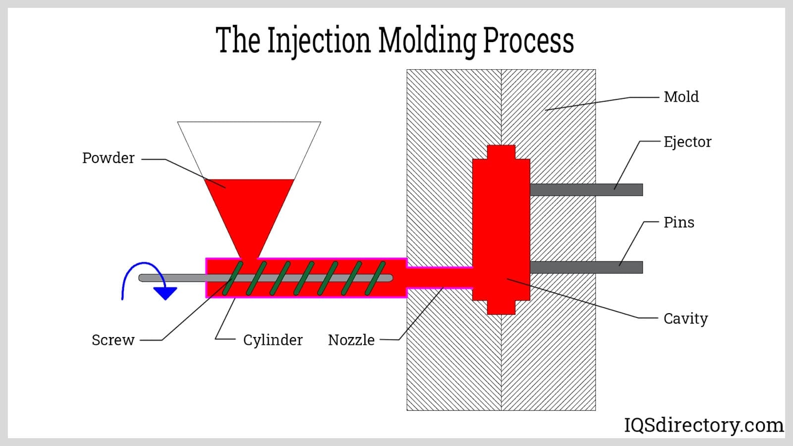
The plastic injection molding process has brought a paradigm shift to manufacturing in that it allows a world of precision to be achieved in mass production of the intricate plastic part. But steady quality only comes through an expert knowledge of injection mold tolerances, which are defined as the permissible variation of nominal dimension tolerance between what you specify in your design, and what you get. This ultimate guide will discuss all you need to know about injection tolerances to make sure your parts can be of specific size and shape each time, adhering to the desired tolerance .
Understanding the Fundamentals of Injection Mold Tolerances
Injection mold tolerances are a measure of the amount of deviation that can be made to nominal that your part will still perform correctly with. Although injection molding by nature is highly precise, there still is the unavoidable variation caused by shrinkage, uneven shrink rates thermal expansion, and mechanical constraints of the materials. These tolerances are important in projects where several components are used and they must have uniform wall thickness to assemble freely without any difficulty.
Tolerance range will just tell you whether your end product components will work as designed. Too slack, and parts will not have an adequate fit, or they will fail to support the structure. Too strict, and production turns gravitatingly costly and even not possible to be arranged ordinarily. The process of coming up with the desired tolerance stack is a great thought that should consider the design requirements, properties of the material, and the capacity of manufacturing to hold tight tolerances.

The tolerances that can be attained by modern injection molding are very high and this precision is not free. Machining operations, special tooling, or high-quality materials might be required in parts with thick walls here the tolerances are extremely tight, which has an additional cost on production. Thus in order to have the optimum quality and cost effectiveness, maintaining tight tolerances and recognizing that uniform cooling is a major factor should be specified even in the space of design.
Machining Tolerances vs. Resin Tolerances: Key Differences
Injection mold tolerances are a measure of the amount of deviation that can be made to nominal that your part will still perform correctly with. Although injection molding by nature is highly precise, there still is the unavoidable variation caused by shrinkage, thermal expansion, and mechanical constraints of the materials. These tolerances are important in projects where several components are used and they must consider material shrinkage in the design phase to assemble freely without any difficulty.
Tolerance range will just tell you whether your end product components will work as designed. Too slack, and parts will not have an adequate fit, or they will fail to support the structure. Too strict, and production turns gravitatingly costly and even not possible to be arranged ordinarily. The process of coming up with the best compromise is a great thought that should consider the design requirements, properties of the material, injection pressure, and the capacity of manufacturing.
The tolerances that can be attained by modern injection molding are very high and this precision is not free. Machining operations, special tooling, or high-quality materials might be required in parts where the tolerances are extremely tight, which has an additional cost on production. Thus in order to have the optimum quality and cost effectiveness, proper tolerance should be specified even in the space of design.
Critical Design Considerations for Tight Tolerances
Knowledge concerning the difference between machining and resin tolerance, along with material selection, is a key to the success of injection molding. These two kinds of tolerances deal with different manufacturing sides and the drawing dimensions of injection molding material possesses different nature that will influence the quality of your final product.
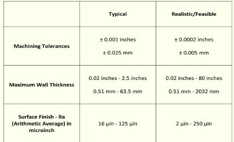
Machining tolerances are described as the tolerance established, in the mold tool itself. The standard injection molding tolerances include typical tolerances, such as machining tolerances in the industry which are general ±0.003 inches (76mm) or so. This tolerance is in respect to the dimensions of the mold cavity and core which are, via the high-precision CNC machining. The quality of the mold machining directly effects how consistent the parts made is over the whole life of the mold.
Resin tolerances are however tolerances and they are on the final molded part and they take note of material behavior in the molding process. These are typically tolerances larger than machining tolerances, usually beginning at 0.002 in per inch (0.051mm/mm), but may differ exceptionally broadly depending on material properties, part design and processing conditions. A resin tolerance should take into consideration the shrinkage variation, including the shrinkage rate, expansion due to heat, and flow properties of plastic materials.
These tolerances are important because of the relationship that exists between them in the production of parts. You cannot get a tighter tolerances with the resin than you can with the machining but optimizing the two within an acceptable range ll provide you with a consistent quality and matching parts that yield to slight variations in your specifications.
Wall Thickness Impact on Dimensional Stability
The first step to a successful injection molding is in its design. Moldable parts have better chances of firm tolerances. There exists some key design parameters that affect the realization of tolerance and once these details are studied early enough in the design process, it will help in producing injection molded parts and avoid costly changes.
The geometry of part is the key to tolerances. The complex geometry such that it has different wall thickness, deep rib or features that are bulky, would be more prone to dimensional variations. And maintaining uniform wall thicknesses by making geometry as simple as possible where it can do so enhances tolerance consistency and lowers production cost, accommodating slight variations . In places where more complex features are required consideration of how the material might flow and be cooled can reduce dimensional variance.
Tolerances are also influenced by the position and orientation of features in the mold. The features near the gate tend to have a better dimensional control owing to an enhanced injection pressure an packing pressure, and those plugged further away may tend to vary. Pattern recognition of material flows aids in the patternization of the feature placement of critical dimensions that can provide consistent result .
An interdependence of a variety of part features should also be taken into account. Tolerances which are conditional upon multiple components, or which involve closely matching independent parts call for close coordination of design and possibly, increasing wall thickness and tighter individual tolerances so as to obtain the assembly fit desired.
Draft Angles and Their Effect on Tolerances
The most probably important design aspect influencing injection mold tolerances is wall thickness uniformity. Variability in the wall thickness results in very tight tolerance and varying cooling rates and thus warpage, sink marks, and dimensional instability that may drive the parts out of their acceptable limits, which plastics typically face .
Cooling of a thick material is very slow as compared to thin section causing internal stresses as the material solidifies and requiring to hold tight tolerances . Such stresses have the potential to result in warpage years after the part has been removed out of the mold which causes dimensional variation that complies with the tolerance requirement, especially if the parts cool properly . Also sections which are thick have a tendency to develop sink marks because the molten center shrinks even after the surface has solidified by drawing the outer surface towards its center.
This is best done by the thickness of the walls remaining constant all over the part, this is usually between 1-3mm, according to the intended application. Transitions between sections with different wall thicknesses should be gradual in order to reduce concentration of stress and to provide improved dimensional stability, including considerations for hole diameter when it is not possible to avoid such variation. Ribs and gussets can serve a role of providing structural support without thickness in walls itself, and thus, the strength is retained and it is dimensional accurate.
Computerized advanced software in simulating cooling has the capability of establishing lines of cooling and probable problem areas in the designing process. This forecasting feature means that designers no longer have to risk huge mold tooling investments until they are sure that they have optimised the distribution of wall thickness according to tolerance requirements with the first production run.
Material Selection and Shrinkage Characteristics
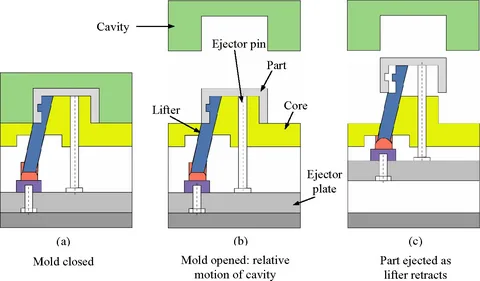
Successful injection molding requires draft angles that first enable the part to be ejected out of the mold and secondly avoids damaging the part or mold. Nevertheless, the draft directly influences dimensions of parts and should be specially taken into consideration when tolerances are given.
Inadequate draft exerts a high ejection pressure which may result in destruction of parts, distortion of dimensions or even surface flaws. On the other hand, more than enough draft can diminish the functionality or appeal of the parts. Most applications require a good draft angle of 1-2 degrees; however specific geometry and/or material choice, and/or surface finish requirements may require variations to this parameter.
Tolerances are influenced by draftsubmit ticks and actually modifying values of vertical surfaces. The draft of a 50mm feature and a draft of 2-degrees leaves a difference of about 1.75mm between the top and bottom size. In the designation of tolerances, this dimensional change is also to be considered so that a part can perform its job properly.
New technologies in the design of molds, like a continuous change of draft angle or no draft areas, are capable of retaining critical dimensions, as well as providing part ejection. These methods can be cost and tooling-intensive but acceptable when strict requirements in the tolerances of a part are needed in the functioning of a part along with temperature and pressure sensors .
Process Control and Scientific Molding Techniques
The material used also significantly affects the tolerances in injection mold due to the differing rates of shrinkage, flow properties and thermal compatibility. The plastic resins exhibit peculiarities in their behaviors that should be comprehended and can be predisposed within the design of the molds for an injection molding project as well as their tolerances.
The process is manifested by shrinking when the molten plastic cools down and solidifies inside the mold. Various materials have varying schedules of shrinkage, as low as 0.002 inches per inch in some engineering plastic to greater than 0.020 inches per inch with some semicrystalline material. This variance should be corrected in a design of the molds in order to get desired dimensions.
To illustrate, an ABS plastic shrinks about 0.003-0.007 inches per inch whereas polypropylene may shrink 0.010-0.025 inches per inch. Change of material without making changes to the design of the mold may lead to parts that are too large or too small on their design specification thereby making them unsuitable.
Shrinkage of crystalline materials tends to be greater and less predictable than that of the amorphous materials. Directional variations in shrinkage may also be observed in semi-crystal material such as polyethylene and polypropylene, where the shrinkage rate is more in the flow direction as compared to that in the cross-flow direction. When tolerances are to be specified on critical dimensions this directional shrinkage must be taken into account.
Critical-to-Quality (CTQ) Features and Tolerance Specification
Stable tolerances can only be attained when there is solid process control using scientific molding. This technique is an optimization of three very important phases of injection molding process fill, pack and hold, to achieve dimensional tolerances . Every step has to be well monitored so that there is dimensional consistency in one part to another and lot to lot.
The fill phase decides on how the molten plastic gets into the mold cavity and fills the cavity. Filling temperature and rate is consistent leading to even distribution of materials and fewer dimensional variations. Optimizing fills refers to a balance between the injection speed, pressure and temperatures that allow the desired cavity to be completely filled without incurring any fill defects or very large dimensional drifts.
The pack stage exerts even more pressure to act as a compensation to shrinkage of materials as they cool down. Adequate pack pressure and timing is critical to dimensional accuracy, especially where there are thick sections that only straighten out after the gate has frozen. Lack of adequate or too much pack pressure leads to undersized parts or flash or dimensional distortion respectively.
The hold phase preserves the pack pressure until the gate solidifies to eliminate back-flow, then prevents the part weight and dimensions. Each material, part geometry, requires hold time to be optimized so as to achieve maximum dimensional stability without unnecessarily long cycles.
Advanced Measurement and Quality Control Methods
Each part feature does not have to be dimensionally precise. Critical to Quality (CTQ) feature identification and prioritization can focus attention in manufacturing on the features of the part that most affect its functional size. It will use minimum controls throughout the process to maximize quality and cost.
CTQ aspects may consist of mating surfaces, mounting holes, etc along with any dimension influencing the assembly or performance of the part itself. Such characteristics ought to be distinctively indicated in part drawings and specifications which are frequently emphasized by special markings or callouts to guarantee that the manufacture takes interest.
Even Requiring statistic process control, or special process measurement procedures, or special tooling features may be necessary to specify tolerance of CTQ features. Though this makes the manufacturing more complex, it guarantees predictable quality in those dimensions which are of chief concern to your application.
Also, the way in which a CTQ features work with general part geometry should be taken into account. Other features that do not impact directly on the performance but affect the dimensions of the feature responsible of the CTQs may also need to be tightened so as to maintain consistency with the very important dimensions.
Troubleshooting Common Tolerance Issues
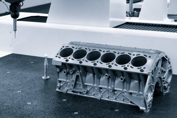
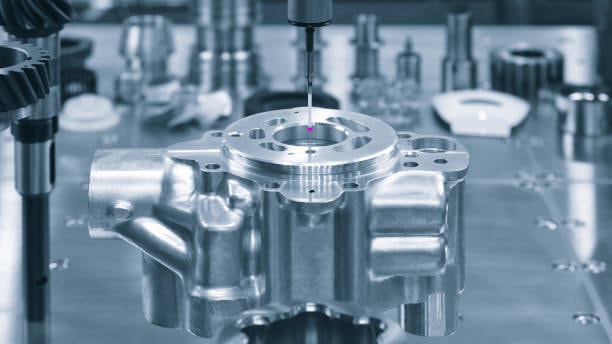
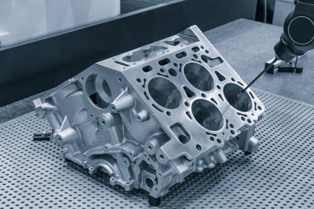
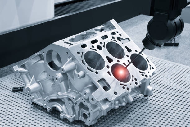
Flawless measurement and quality control systems are necessary in achieving tight tolerance. Contemporary injection molding plants use multiple measurement technologies that can accommodate extreme temperature variations to keep part dimensions within relevant tolerances during the production runs.
The coordinate measuring machines (CMMs) offer an accurate measurement of complicated shapes of music equipment, meaning that it is possible to check the dimensions of multiple parts at once. By measuring the distance between features that are very subtle in screws, CMM measure can help to notice slight dimensional variations that may signify process related drift or tool wearing that could result in correctional measures being made before the process results in parts out of tolerance.
Visions systems are fast and automated measurement procedures, which are good in large volume production. These systems are able to quantify a number of features simultaneously and to also give real time feedback that can be used to control the process. State-of-the-art vision systems have the ability to reveal dimensional tendencies and give the heads-up when corrections are due.
Sources of dimensional variations can be determined and worked upon with the help of statistical process control (SPC) methods. Techniques incorporated in SPC systems do this by monitoring critical dimensions over a period in order to determine whether the noticeable changes in the process are related to natural variations or one that needs investigation. In such a way, it is possible to guarantee the quality of the process and reduce useless modification of processes.
Cost Considerations and Tolerance Optimization
Tolerance problems may arise even when a thorough design and process control have been practiced. Looking at problems that are common and how they can be overcome can ensure quality in production and reduce the downtime when problems set in.
Tolerance issues especially caused by warpage are very common and are usually caused by unequal cooling or internal stress. The solutions can be designing cooling system differently, varying parameters in the process or redesigning part geometry to reduce stress concentration. Warpage issues usually have such problems that need systematic investigation to find their root causes.
The existence of dimensional drift with time can reveal either tool wear, process unsteadiness or material inconsistency. Monitoring of some of the important dimensions on a regular basis allows detection of trends prior to causing out-of-tolerance components. Minimizing the dimensional drift is assisted by preventive maintenance programs and standardization of processes.
Potential Tolerance achievement based on flash or short cutting can alter dimension ofparts or the features may be left incomplete. Most of the problem is caused by an inappropriate process parameter or tool maintenance. Methodical diagnosis procedures allow addressing and mitigating the origin of problems.
Future Trends in Injection Molding Tolerance Control
The injection molding sector is still changing under new technologies and methods of making improvements in terms of tolerance. The idea of industry 4.0 is applied to injection molding that introduces the concepts of advanced sensors, data analytics, and machine learning to struggle with tolerance.
Subtle changes in the conditions of the process making a difference in parts dimensions can be monitored using real-time process monitoring systems. Such systems allow proactive actions that ensure tolerance compliance, and it does not need manual applications. Tolerance problems could be predicted and prevented with the help of advanced algorithms that learn by past data.
Additive manufacturing Injection mold Injection mold tooling has become popular in additive manufacturing to produce complex cooling channel and conformal cooling systems. The enhanced cooling designs have the potential to enhance dimensional control, and their potential to regulate thermal gradients is better than conventional cooling strategies.
Digital twin will facilitate optimization of processes online so that molding can be optimized online even before the manufacturing process starts physically. The ability allows tolerance optimization at the design level which would otherwise be done by using trial and error methods which prove to be expensive in the initial periods of the production start.
Conclusion
Tolerance on injection mold is a vital learning step in manufacturing plastic parts. How the design is considered, what material is used, what process is controlled, ensures that your parts can have meet the critical dimensional requirements. Making use of the principles of machining and resin tolerances, part design to enhance prodabilty, suiting materials and effective process control, manufacturers can easily meet the tight tolerances in the modern application.
Tolerance management needs to be carried out systematically that starts with the design optimisation and proceed through monitoring and quality control of production. It is time-saving, cost-effective and will help you deliver injection molded components that will flood your customers with your products to be used and used and used all during the projected service life of your component.