Geometric Dimensioning and Tolerance (GD&T), which encompasses geometric tolerance, is one of the most important features of contemporary production that ensures that parts to be produced meet strictly specifications and would perform correctly within the intended uses. Flatness is one of those GD&T controls which is a basic tolerance that has a direct bearing on the product quality and assembly as well as manufacturing efficiency common method. This is a comprehensive guide about flatness in GD&T, including simple principles, advanced implementations and measurement practices.
What is Flatness in GD&T?
Flatness is a Geometric Dimensioning and Tolerancing (GD&T) tolerance which specifies the permitted error on a set of surfaces, including surface finish, which is not perfectly flat. As opposed to dimensional tolerances, which govern size, flatness is used to deal specifically with form deviation, to keep surfaces at their proper, desired geometric shape within an allowable tolerance two methods.
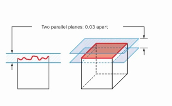
It describes two parallel virtual planes on both sides of the flat surface as the tolerance zone of the surface. In order to approve the part, all the points on the given surface must be within these two planes. This type of geometric control is critical to use where the uniformity of the surface directly influences functionality, e.g. sealing surfaces, mounting interfaces and precision mechanical assemblies dial gauge.
The flatness tolerance value is independent of other geometry details, in the sense that it does not compare the surface form to any external datus or coordinates system, it only compares the housed features. It allows flatness to be also particularly useful in the control of local surface quality and a flexibility of design in terms of overall orientation and location of parts.
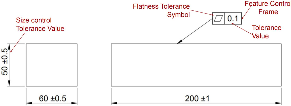
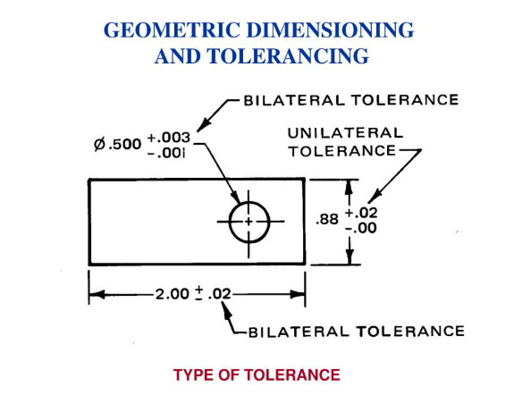
The Flatness Symbol and Callout Structure
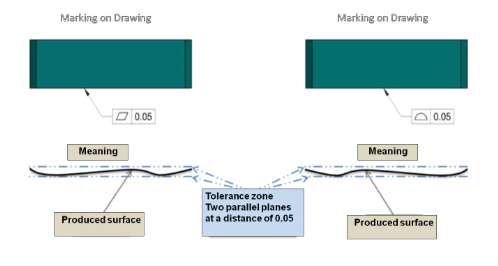
The GD&T symbol that shows typical flatness callout is symbolized as a parallelogram ( \(\oslash\) ), whereas representatively the tolerance zone is implied by parallels planes. This symbol is in the feature control frame along with the value of tolerance, so there is a standard and clear way of indicating the requirements of flatness.
The geometric characteristic symbol is followed and a typical flatness call out will be written as the tolerance value. Flatness uses the minimum zone method and no datum references similar to many other GD&T controls because surface form is being judged. The tolerance value gives the maximum permissible distance between the two parallel planes which had defined the tolerance zone.
The use of flatness callouts in engineering drawings has conventions, including the concept of tolerance stacks . The feature control frame may be directly associated with the surface by a leader line, may be on an extension line of the surface, or may be beside the surface dimension. Callout Locations and Placement A good location and placement of a callout will make its intent abundantly clear and will avoid confusing the manufacturing process flatness refines.
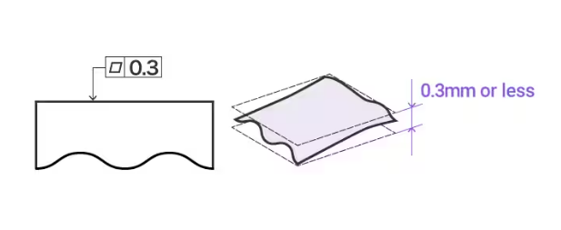
Understanding the Flatness Tolerance Zone
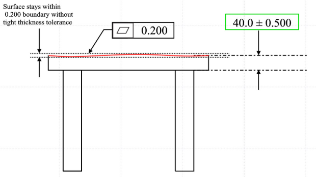
The flatness tolerance is given in reference to two parallel planes (parallel with the surface which it is called out against) which establishes an area within which the whole of the reference surface and size dimension should be. This concept of a three-dimensional tolerance zone is central towards determining the manner in which flatness manages deviation of the form of the surface.
The tolerance zone thickness is the stated value of flatness, which forms an inner position where all the surface points must be located in. These parallel planes are also kept parallel to the overall orientation of the surface regardless of the position or angle of a surface to other features of the parts, which may require tighter tolerance create virtual planes . It becomes possible through this feature that without compromising the selection of the overall part orientation, a surface form can be dictated by flatness.
The effectiveness of the tolerance zone resides in the use of accurate measurement, adequate surface sampling and assessment techniques. Surface variations are inevitably produced when manufacturing processes are applied, and flatness tolerance zone accepts such variations, but still in conformity with the functional specifications. Practising this concept assists the engineers in making suitable tolerance values that are balanced in the manufacturing ability and in the functions which are needed maximum deviation.
Applications of Flatness in Manufacturing
The control of flatness is very widely used in a wide variety of manufacturing industries, especially precision machining, aerospace, automotive, and electronic industries. Typical uses are in covering over a surface where even contact is essential, as in mounting surfaces where even loading is essential, and in optical surfaces where any departure or flatness has to be minimized.
In mechanical assemblies, flat tolerances are a key aspect of form control that is necessary in order to have a good mating condition between two components so that a stress concentration cannot work and cause failure sooner flatness control applies. As an example, engine block deck surfaces need thorough control of flatness where they determine right sealing of the gasket and no combustion leakage. The same case applies to precision measurement tools that depend on a flat working surface to calibrate and work best.
Flatness control of printed circuit board substrates, heat sink mounting surfaces, and semiconductor packaging is essential to evaluate flatness, which are common uses of electronics industry. The applications have very stringent flatness requirements since it is essential to have good electrical connection, heat dissipation, and reliability of the components.
Flatness Applied to Surfaces vs. Features of Size
Flatness may be used on a complete feature, including the straightness flatness (in case of a sheet metal plate) or to the surface of a component. When flatness is used on a surface of a part it should always be less than the dimension tolerance. It may in fact be greater when it is applied to a feature of size however.
In its application to planar surface, flatness regulates the shape of the actual surface topography with all the points falling within the prescribed tolerance band. This is the typical and simple application of this and normally applied in controlling the quality of individual surfaces without seeking the relationship with other geometric characteristics.
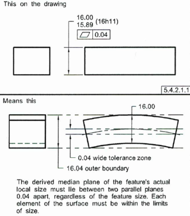
Flatness of features of size complicates the matter further though the derived median plane (DMP) and not the surface is controlled. This program can be of great use when it comes to managing the shape of thin walls, plates, etc. due to tight control of the shape and thickness variation, as well as to control bending.
The difference between the two point measurement of surface size application and feature of size has serious consequences as to the techniques in inspection and production means. Surface flatness would demand that the actual surface be measured whereas feature of size flatness would demand that the median plane is calculated and its form characteristics are gauged specified tolerance zone.
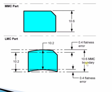
Material Condition Modifiers with Flatness in gd t
In cases of applying flatness to aspects of size, then material condition modifiers (Maximum Material Condition – MMC, and Least Material Condition – LMC) apply. These add-ons, introduce functional tolerance relationships between the size tolerances and form therefore, enabling a greater form deviation as the feature changes out of the required condition in the material.
Flatness in the use of MMC modifier contributes manufacturing flexibility by enabling further form deviation where the feature size is permit. The correlation indicates the practical functional reality in which minor variations on the forms can be admitted at the expense of changes in size with the other being within acceptable ranges.
The use of LMC modifiers on flatness is usually against minimal material requirements on structural integrity, or functional performance. This app maintains sufficient material distribution and has moderation of the shapes of all overall features to conserve design purpose and functionality necessities.
Local Flatness Per Unit Area
Local flatness control takes account of those local area requirements that may be different to overall surface flatness requirements. This will be especially useful when the area covered is huge and it may not be feasible or required to have very close overall flatness to perform the correct functional actions.
The local flatness specifications put their tolerances limitation on certain areas of the surface, specifying tolerances as flatness per unit length or diameter. Take a simple example, a specification can say that the required flatness is 0.05mm flatness/25mm diameter which is enough local surface to be good enough, but still allow some overall variation of the surface.
The method makes practical compromises in manufacturing to suit functional needs especially where the local and not the global form of the surface is sufficient as in the example of gasket seating surfaces. Local flatness must also be inspected through conducting systematic sampling of the whole surface, in order to ensure compliance of all feasible local zones.
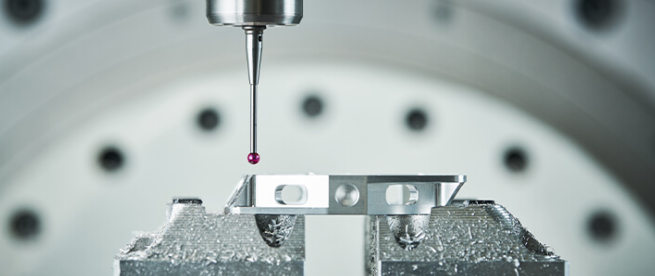
Measurement Methods for Flatness Evaluation
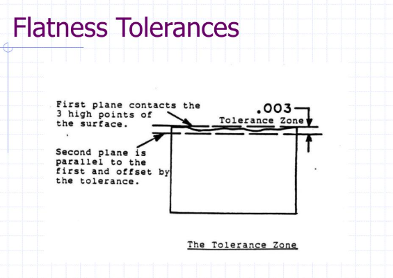
One of the ways to measure flatness in GD&T is given by a height gauge. The part is operated with the bottom, surface resting on three columns with the same height. These columns are then adjusted in heights by the operator to create an illusion of a perfectly flat plane. This conventional solution has sufficient precision in most applications, is affordable and has availability.
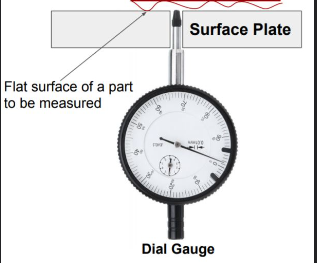
Another so frequently common strategy is the surface plate measurement; where precise granite or steel plates are put under use as measuring dishes. They take samples on a surface plate and dial indicators see how far things vary on the surface. In this technique, proximity of surfaces and leveling of the surfaces is a critical aspect in coming up with the right results.
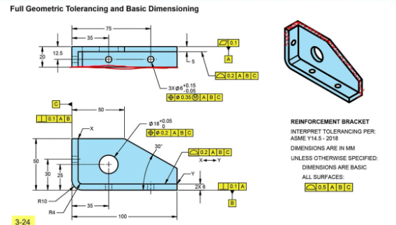
It is stated in the ASME Y14.5 standard, as follows,: it is specified as a tolerance area delimited by two parallel planes that the surface must be somewhere within. Bar none, Coordinate Measuring Machines (CMMs) offer the most complete and perfect flatness analysis proficiencies as they use advanced software algorithms to process and evaluate point cloud data and conclude whether they meet their designated tolerances or not.
Advanced CMM Measurement Techniques
These CMM systems that are current use different algorithms in flatness measurement and each has got some advantage unlike the other after considering the needs of the application. The method of finding the best fit plane determines a plane that minimises total deviation of a measured surface points to a plane, statistical method to measure of flatness.
Minimum zone algorithm identifies a zone with the minimum size between two parallel planes covering all of the measured points. This method is identical to the GD&T definition of flatness and normally gives more conservative values than best-fit computation.
The sampling methods are considerably influential in measuring reliability and accuracy. The allocation of the points properly allows representative surface evaluation minimizing the time of measuring. The new CMM software can optimize sampling patterns on geometry and on tolerances, making it both more efficient and accurate.
Flatness vs. Straightness: Key Differences
This difference between flatness and straightness generates confusion to the engineers and manufacturers. The most of the GD&T criteria are basic, like flatness, which makes sure that surfaces are smooth and without waviness, which is very important to the assembly and functionality of mechanical parts, straightness regulates linear characteristics or axis.
Flatness works in three dimensions, in the control of an entire form of the surface in a region of parallel planes. Straightness on the other hand coordinates straight features in a cylindrical or planar tolerance zone depending on its usage. This basic distinction influences both the operation and measurement methods, as well as functional connotations.
These controls are also dissimilar in application contexts. Flatness generally provides surface contact, sealing, and mounting specifications, and straightness offers straightness in the axis of alignment and linear motion as well as assembly fit requirements. The knowledge of these differences allows one to make adequate choices in selection and use of tolerance.
Industry Standards and Best Practices
The most highly used North American standard that guides the application and interpretation of flatness is ASME Y14.5 which has extensive rules over use of symbols, tolerance, and principles of measurement. Similar advice is given in international standards such as ISO GPS (Geometrical product specifications) but with regional differences.
Specification of flatness can be done in the best practice level involving considering the manufacturing possibilities, functional needs, as well as accessibility of measurements in the design stage. Unrealistic tightness in tolerences is generally a cost in terms of the manufacturing process and does not necessarily benefit the functionality whereas lack of control can affect the performance.
The state of documentation must show the need of taking measurements, sampling approaches and acceptance rules. Correct drawing notes and particulars eliminate interpretation errors and makes it possible to have uniform quality assessment in various manufacturing places and inspection staff..
Manufacturing Process Considerations
The various manufacturing processes have varying capacities of meeting the flatness requirements. Machining processes such as face milling, grinding, and fly cutting would usually achieve good control of flatness, although sometimes they benefit by special tooling and mounting.
The flatness control of casting and forging possess their own issues and usually must undergo secondary machining to meet final fitting specifications. Where flatness is important to functionality, capability and cost implications should be considered in the process selection.
Stress relieving and heat treatment operations have a large effect on flatness especially on thin walled or oversized parts. The effects should be taken into consideration during design and manufacturing planning and possibly considerations to correct post process means to stay in specs.
Quality Control and Inspection Planning
Controlling flatness also demands of good planning of inspections based on geometry of parts, tolerances involved and the type of measuring equipment present. Appropriate levels of coverage of the surface should be provided by the sampling plans without giving unacceptable costs and inspection times.
Frequency of Inspection Process stability and part criticality and customer necessities determine the frequency with which they are inspected. These techniques of statistical process control can be used to reduce inspection frequency and still be sure that all parts of the best quality. Analysis of trends in the measurements of flatness usually betrays some opportunities in the improvement of the processes.
Requirements of documentation and traceability depend by industry and application. Demanding applications in aerospace and medical devices will generally require complete records of the measurements, whereas the less demanding applications would be okay accepting simplistic documentation methods.
Conclusion
Flatness is a vital master control geometrical indicator of GD&T since it guarantees the surface characteristics and functionality in varying manufacturing activities. Engineers develop a feel of its correct usage and methods of measuring and the correlation it has with other geometric controls which helps them to know the correct tolerance to use striking a balance between its functionality as well as practicality in manufacture.
Measuring technology advancement also contributes to higher and faster accuracy and efficiency in flatness evaluation technology especially in the use of CMMs and complex software algorithms. The benefits achieved by these advances are a more precise control of the process, and improved quality of the product, and a decrease in costs of inspections, and cycle time.