Introduction
In CNC (Computer Numerical Control) machining, precision and accuracy are important to assuring high-quality manufacturing. One crucial component that promotes machining precision is tool radius correction. Without this capability, the programmed toolpath might not line perfectly with the actual cut due to the physical dimensions of the tool. Tool radius compensation allows CNC machines to account for the cutter’s diameter, ensuring that the final product follows design parameters with little variance.
This thorough book will cover the principles of tool radius compensation, how it works, the benefits of adopting it, frequent challenges experienced by machinists, and best practices for optimizing CNC machining using tool nose radius compensation.
What is Tool Radius Compensation?
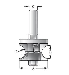
Tool radius compensation is a CNC function that adjusts the toolpath to account for the actual diameter of the cutter. Since cutting tools have a defined width, designing a toolpath without compensation could lead to mistakes in part dimensions.
When tool radius compensation is activated, the CNC machine moves the tool slightly away from the programmed path route to ensure the cutting edge follows the correct contour. This is particularly critical in milling processes, where both internal and external geometries must be perfectly machined.
The two basic G-code commands utilized for tool radius compensation are:
- G41 – Left compensation: The tool advances to the left of the programmed toolpath.
- G42 – Right compensation: The tool advances to the right of the programmed toolpath.
- G40 – Cancels tool compensation, guaranteeing no offset remains.
The choice between G41 and G42 depends on the tool’s direction of movement relative to the workpiece. Using varying tool sizes, these codes let machinists dynamically change cutter paths, allowing modifications without having to change the whole G-code program.
How Tool Radius Compensation Works
When tool radius compensation is applied, the CNC machine adjusts the toolpath by half of a point of the tool diameter in the proper direction. This procedure involves numerous steps:
- Determining the Cutter Offset: The CNC operator enters the tool’s diameter into the controller’s tool table.
- Activating Compensation: Using G41 or G42, the machine adjusts the toolpath by adjusting the tool’s centerline to suit the radius.
- To stop sudden changes in tool position, compensation should start on a straight segment instead of inside a curve or turn.
- Maintaining Compensation Throughout Machining: The compensation remains active as long as needed, guaranteeing consistent offsets.
- Deactivating Compensation with G40: Once machining is complete, G40 deactivate the compensation to avoid unexpected tool movements.
Proper execution of these stages ensures that tool radius compensation works successfully, resulting to better machining precision.
Benefits of Tool Radius Compensation
Using tool radius compensation gives various advantages that boost CNC machining efficiency:
1. Improved Accuracy
By adjusting for the tool’s diameter, CNC machines manufacture parts that precisely match the specified dimensions. This avoids errors caused by improper toolpaths, providing high-quality finishes and accurate tolerances.
2. Tool Wear Adjustments
Over time, cutting instruments acquire wear, which alters their effective diameter. By changing the tool diameter in the CNC controller, tool radius compensation may dynamically change to account for wear, improving tool life and preserving accuracy.
3. Simplified Programming
Instead of manually altering toolpaths in the CAM (Computer-Aided Manufacturing) software, machinists can utilize standard toolpaths and rely on compensation to accommodate for different tool diameters. This decreases programming complexity and makes it easier to shift tools when needed.
4. Reduction in Setup Time
Tool radius compensation allows machinists to exchange tools without reprogramming the entire part. This speeds up the setup procedure and lowers downtime, therefore improving the production efficiency.
5. Enhanced Machining Flexibility
When dealing with complex shapes and varied materials, compensation allows flexibility in modifying the toolpath dynamically. Industries needing high-precision machining, including aerospace and automobile production, may find the tool offset this particularly helpful.
Common Errors and Troubleshooting in Tool Radius Compensation
Though tool radius compensation has advantages, inappropriate application of it might cause machining mistakes diameter offset. Some frequent difficulties include:
1. Incorrect Compensation Direction (G41/G42 Mix-Up)
Using the wrong compensation direction results in incorrect cuts. If the tip of the tool is offset in the wrong direction, it may cut outside or inside the intended path, causing part defects cutter comp.
Solution: Always validate the right G41 or G42 command based on the tool’s movement direction relative to the workpiece
2. Engaging Compensation on a Curved Path
If compensation is applied on a curved path, it might create sudden tool position changes, leading to surface defects.
Solution: Initiate compensating on a straight lead-in path before transitioning into curves or contours.
3. Incorrect Tool Diameter Input
Entering an erroneous tool diameter in the CNC controller results in inappropriate offsets, leading to dimensional mistakes actual tool path offset direction.
Solution: Double-check the tool diameter and ensure it matches the actual cutter in use.
4. Premature Deactivation of G40
Canceling tool compensation too early might lead to unexpected tool movements, possibly injuring the part or creating collisions.
Solution: Always disengage compensation once the tool has entirely vacated the tool tip of the workpiece.
5. Issues with Sharp Corners and Complex Geometries
If tool radius compensation is not applied correctly, it may result in overcuts or gouging at sharp corners.
Solution: Use smooth lead-ins and lead-outs to prevent abrupt changes in tool movement.
Best Practices for Optimizing Tool Radius Compensation
To obtain the greatest results while employing tool radius compensation, adopt these best practices:
- Maintain an Up-to-Date Tool Library: Regularly update tool diameter values in the CNC machine to account for wear and different cutters.
- Perform Test Runs and Simulations: Before cutting important pieces, run simulations to check that the compensation settings give the intended results.
- Use gradual lead-ins and lead-outs to avoid either engaging or disengaging compensation on curves to minimize tool movement errors.
- Regularly Inspect and Replace Worn Tools: Ensuring that tools are in good condition minimizes improper offsets caused by worn-out cutters.
- Train Operators on Compensation Techniques: Proper training ensures that machinists understand when and how to apply G41, G42, and G40 effectively.
Conclusion
Tool radius compensation is an essential operation in CNC machining that improves precision, enhances tool life, and simplifies programming. By properly utilizing G41 and G42, machinists may dynamically alter toolpaths to account for cutter diameters, assuring accurate cuts and high-quality finished products.
Although tool radius compensation has several benefits, inappropriate application can cause mistakes including erroneous offsets and sudden tool movement. Following best practices—such as using smooth lead-ins, checking tool diameter inputs, and executing test simulations—helps mitigate these difficulties and enhance machining efficiency.

